Optoelectronic component

a technology of optoelectronic components and components, applied in the field of optoelectronic components, can solve the problem of increasing the production effort of organic light-emitting diodes

Active Publication Date: 2018-05-22
DOLYA HOLDCO 5 LTD
View PDF12 Cites 0 Cited by
  • Summary
  • Abstract
  • Description
  • Claims
  • Application Information

AI Technical Summary

Benefits of technology

[0005]Embodiments of the invention provide an improved optoelectronic component, with an organic light-emitting diode in which a colour location of the optoelectronic component is changeable. Further embodiments provide an advantageous method for operating the optoelectronic component.
[0013]Due to the feature of the liquid crystal element of selectively reflecting light of the first wavelength range in the first state, light from the first wavelength range is additionally added to the emission spectrum in the first state. This advantageously causes the colour location of the radiation emitted by the optoelectronic component to shift in the direction of the first wavelength range, which is selectively reflected by the liquid crystal element in the first state. The colour location of the radiation emitted through the main emission surface can thus be changed from the first state into the second state or from the second state into the first state by switching the liquid crystal element. The change in colour location advantageously ensues in the optoelectronic component with no separate activation of the plurality of organic light-emitting layers. The organic light-emitting layers thus do not need to be separately electrically contactable, which advantageously reduces the production effort for the organic light-emitting diode.
[0015]In a preferred configuration a light emitted through the main emission surface has a lower colour temperature in the first state than in the second state. It can in particular be provided that the organic light-emitting diode is set up to emit cool white light, i.e. white light with a comparatively high colour temperature. The spectrum of the emitted radiation of the organic light-emitting diode emitting cool white light has a comparatively high proportion of the blue spectrum. In the first state of the liquid crystal element, the back reflection of the yellow light emitted by the organic LED increases the yellow component in the emitted spectrum, thus reducing the colour temperature of the emitted radiation. This in particular causes the optoelectronic component in the second state to emit the non-impacted cool white emission spectrum of the organic light-emitting diode, whereas warm white light is emitted in the first state due to the increase of the yellow component in the emitted spectrum.
[0017]However, with regard to the principle proposed here, it can be advantageous to arrange the side with the stronger light emission in the direction of the rear side on which the liquid crystal element is arranged. As only a comparatively low proportion of the radiation is emitted to the front side and a larger proportion to the rear side in this case, due to the orientation of the organic light-emitting diode, the selective reflection of the radiation from the first wavelength range towards the main emission surface in the first state has a particularly strong impact on the emitted overall radiation when switching between the first state and the second state. In this embodiment, a particularly large shift of the colour location of the emitted radiation can be achieved.
[0018]In an alternative embodiment the organic light-emitting diode has an asymmetrical light emission, wherein more radiation is emitted towards the main emission surface than towards the rear side. In this configuration a stronger emission to the main emission surface and thus a stronger luminosity is achieved. As, however, only a low proportion of the emitted radiation is emitted towards the rear side, the impact of the addition of the radiation of the first wavelength range by selective reflection on the rear side in the first state is perceptibly lower than in the previously described embodiment. The configuration in which the organic light-emitting diode is oriented in such a way that the side with the stronger light emission faces the main emission surface is then advantageous when a great deal of luminosity is intended to be achieved and only a comparatively small shift of the colour location and / or the colour temperature is intended to be achieved by switching between the first state and second state.
[0019]According to an embodiment of a method for operating the optoelectronic component, the liquid crystal element for changing the colour temperature of the radiation emitted by the optoelectronic component is switched from the first state into the second state or from the second state into the first state by means of a voltage source. For example, a cholesteric liquid crystal element can be switched from the first state with a planar texture into the second state with a focal conic texture or vice versa by applying an electrical voltage to the liquid crystal element by means of the voltage source. The cholesteric liquid crystal element is advantageously bistable, i.e. an electrical voltage need only be applied for switching between the first state and the second state or vice versa. The method thus allows the colour location of the radiation emitted by the optoelectronic component to be adjusted in an energy-efficient manner.

Problems solved by technology

However, this increases the production effort for the organic light-emitting diode.

Method used


Image

  • Optoelectronic component
  • Optoelectronic component
  • Optoelectronic component

Examples


first embodiment

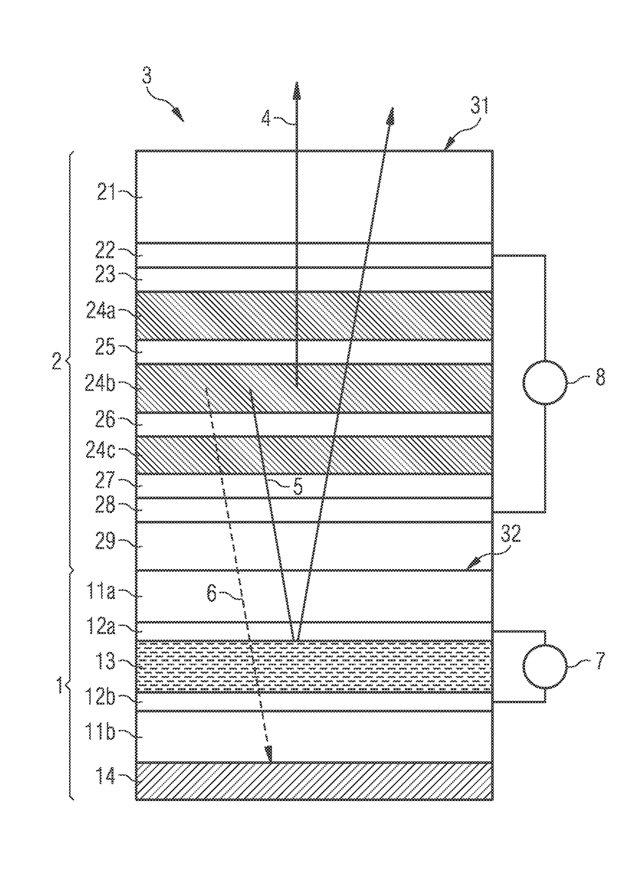
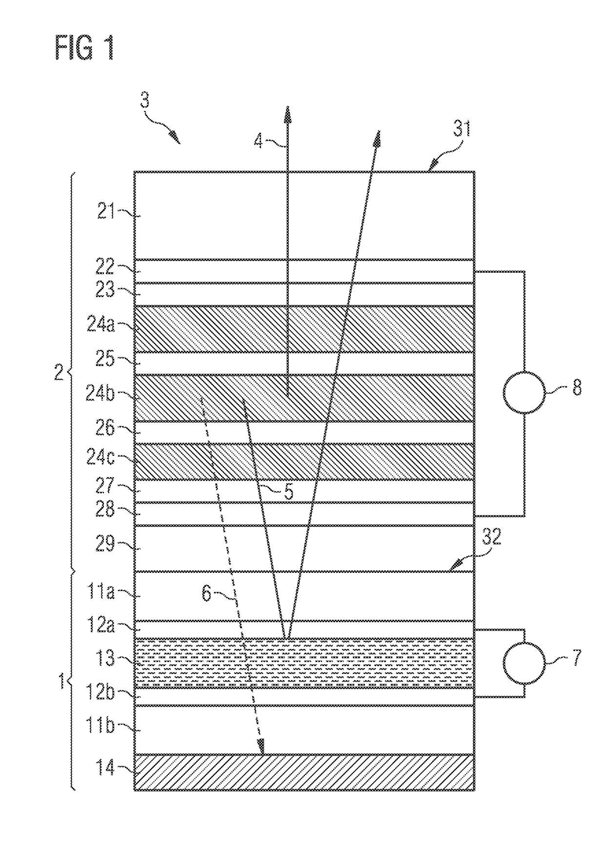
[0029] the optoelectronic component 3 shown in FIG. 1 has an organic light-emitting diode 2, which is provided for emitting radiation 4 through a main emission surface 31. The organic light-emitting diode 2 is preferably a white light emitting organic light-emitting diode, in which the white light is generated by additive colour mixing of the radiation emitted by a plurality of organic light-emitting layers 24a, 24b, 24c.

[0030]In order to generate white light, the organic light-emitting diode 2 has at least two, or preferably at least three, organic light-emitting layers 24a, 24b, 24c. For example, the organic light-emitting diode 2 can have a first organic light-emitting layer 24a for emitting blue light, a second organic light-emitting layer 24b for emitting green light and a third organic light-emitting layer 24c for emitting red light. The plurality of organic light-emitting layers 24a, 24b, 24c is arranged on top of each other in the layer stack of the organic light-emitting d...

second exemplary embodiment

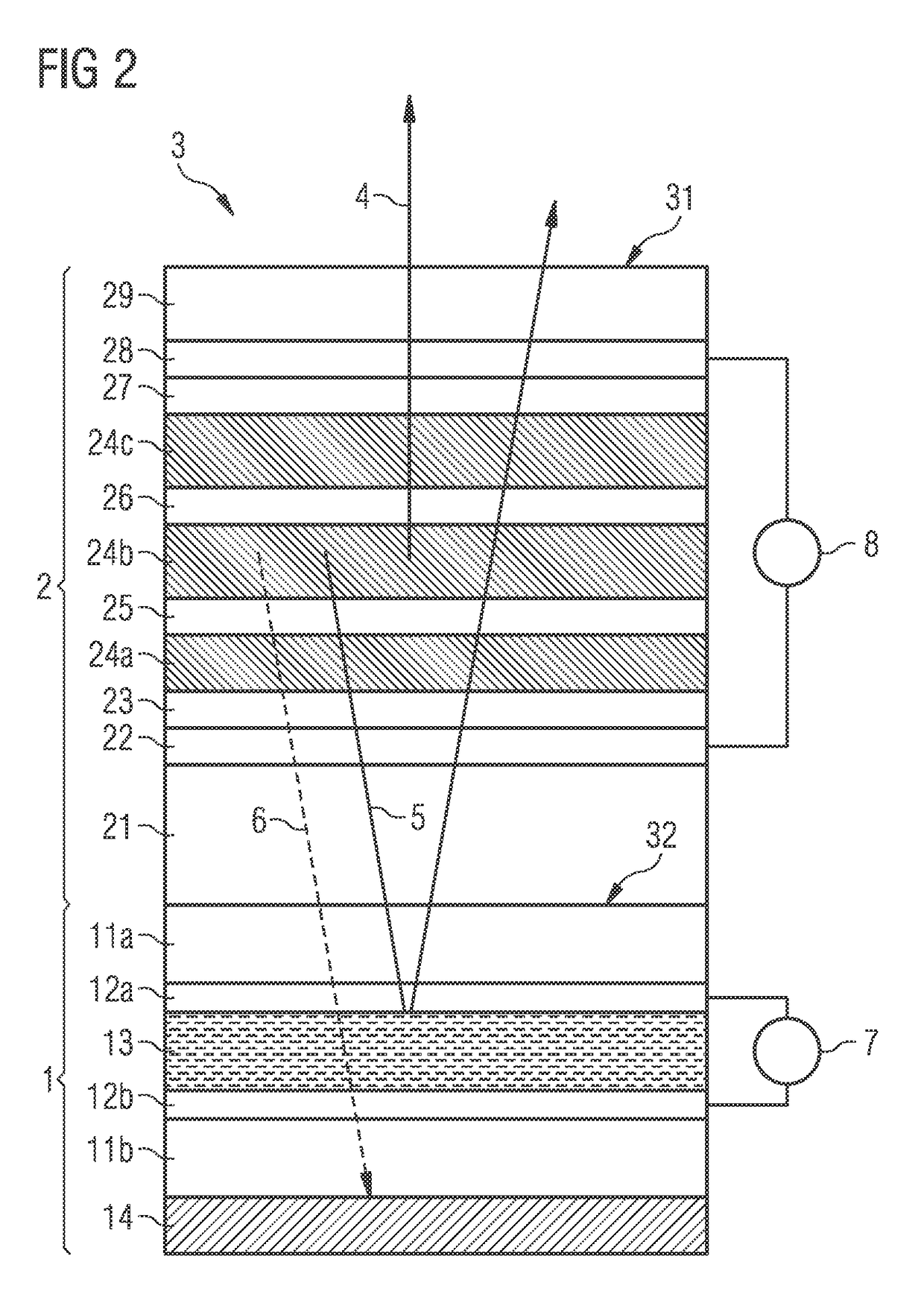
[0046]It can therefore be advantageous to orient the organic light-emitting diode 2 towards the liquid crystal element 1 in such a way that the stronger emission of the organic light-emitting diode 2 ensues towards the rear side 32. Such an exemplary embodiment is shown in FIG. 2. In this exemplary embodiment the organic light-emitting diode 2 is structured as in the first exemplary embodiment, but rotated by 180° vis-à-vis the liquid crystal element 1 compared with the first exemplary embodiment. In the second exemplary embodiment the substrate 21 of the organic light-emitting diode 2 thus faces the liquid crystal element 1 and an opposite surface of the transparent encapsulation 29 forms the main emission surface 31. In this exemplary embodiment, for example, it may be provided that a maximum of 40%, advantageously a maximum of 35% or preferably a maximum of 30% of the emitted radiation is emitted towards the main emission surface 31 and correspondingly a minimum of 60%, advantage...


PUM

PropertyMeasurementUnit
frequencyaaaaaaaaaa
wavelengthaaaaaaaaaa
optoelectronicaaaaaaaaaa

Abstract

An optoelectronic component and a method to operate the optoelectronic component are disclosed. In an embodiment the optoelectronic component includes an organic light-emitting diode configured to emit radiation through a main emission surface and a liquid crystal element configured to adjust a color location of the radiation, wherein the liquid crystal element is switchable into a first state and into a second state, wherein the liquid crystal element in the first state is suitable for selectively reflecting light of a first wavelength range and in the second state is transparent, and wherein the liquid crystal element is arranged on a rear side of the organic light-emitting diode facing the main emission surface so that light of the first wavelength range that is emitted towards the rear side is at least partially reflected in a direction of the main emission surface in the first state of the liquid crystal element.

Description

[0001]This patent application is a national phase filing under section 371 of PCT / EP2015 / 050246, filed Jan. 8, 2015, which claims the priority of German patent application 10 2014 100 253.9, filed Jan. 10, 2014, each of which is incorporated herein by reference in its entirety.TECHNICAL FIELD[0002]The invention relates to an optoelectronic component, which in particular comprises an organic light-emitting diode.BACKGROUND[0003]An organic light-emitting diode (OLED), which emits a mixed colour, in particular white light, can for example be achieved in that a plurality of organic light-emitting layers are arranged on top of each other in a layer stack. A white light emitting organic light-emitting diode can, for example, have organic light-emitting layers for the colours blue, green and red. The plurality of light-emitting layers can be arranged next to each other instead of on top of each other.[0004]A variation of the colour location in an organic light-emitting diode, which has a p...

Claims


Application Information

Patent Timeline
Patent Type & Authority Patents(United States)
IPC IPC(8): H01L27/32H01L51/52G02F1/137H01L51/50
CPCH01L27/3232G02F1/137H01L51/5284H01L51/504H01L51/5281H01L51/5271H10K59/50H10K50/13H10K59/8792H10K59/878H10K50/865H10K50/86H10K50/856
Inventor DIEKMANN, KARSTENSCHWAMB, PHILIPP
Owner DOLYA HOLDCO 5 LTD
Why Eureka
Try Eureka