Flying all-terrain vehicle

Inactive Publication Date: 2007-02-01
HOWARD KENNETH D
View PDF8 Cites 60 Cited by
  • Summary
  • Abstract
  • Description
  • Claims
  • Application Information

AI Technical Summary

Benefits of technology

[0022] In some forms of the invention, the vehicle may include separate air and ground power apparatuses for operation in the air and on the ground. It is preferred that the propeller of the power parachute apparatus be separately driven so that it can be shut down during operation of the vehicle in ground mode, because government regulations do not allow operation of the propeller while the vehicle is operating on a road surface. In some forms of the invention, it may be desirable to operate the ground power apparatus during take-off in the powered parachute operating mode, in order to reduce the time and distance required for achieving airborne flight.
[0027] In some forms of the invention, the vehicle includes a chassis, and a ground power apparatus operatively attached to the chassis, with the ground power apparatus including three or more wheels, at least one of which is steerable, and at least one of which is powered. A suspension system may operatively connect the wheels to the chassis. The suspension system may include adjustable suspension elements, such as pneumatic shocks or struts, which can be adjusted to provide desired ride or handling characteristics, or to raise or lower the chassis with respect to the ground. It may be desirable, for example, to increase the stiffness of the suspension during take-off and landing, and then reduce the stiffness during ground operation to provide a softer ride or better handling while on the ground.
[0033] The lower portion of the prop shroud may be omitted in some embodiments of the vehicle, rather than being a complete circle as in prior powered parachutes. Omitting the lower portion of the prop shroud is advantageous in that it provides more ground clearance during ground powered operation as an ATV, and precludes having the lower portion of the prop shroud becoming caught on objects protruding from the ground. In embodiments having an articulated secondary frame at the rear of a main frame, omitting the lower portion of the prop shroud provides more clearance for the secondary frame and ground power engine, etc., to move upward when the ATV is traveling over uneven ground.
[0037] The vehicle may also include a glide shield to provide improved fuel economy in the flight mode, and lower engine RPM, to increase engine life, in addition to improving the glide ratio. In some forms of the invention, the vehicle includes a floor pan under the main frame, or other structures which are shaped to function also as a glide shield.

Problems solved by technology

Previous attempts and approaches to producing a flying ATV have been purely conceptual, or have proved to be either impractical or unworkable.
The drawings of the Preston application are cartoon-like conceptual sketches, at best, and are non-enabling with regard to adequately teaching those skilled in the art how to practice the concepts disclosed in Preston's application.
In addition to being non-enabling and only disclosing a concept for the construction and operation of the purported multimodal deployable vehicle, the application of Preston further discloses an unworkable concept for converting a ram air parachute, of the type utilized for dropping the multimodal vehicle from an aircraft, for use as a parachute capable of allowing the multimodal vehicle to lift off from the ground under its own power.
As a result, those skilled in the art would also readily recognize that a parachute heavy enough to allow such in-flight deployment, would be far too heavy to be inflated by an air propeller of such a multimodal vehicle attempting to take off from the ground.
While these propeller-driven machines purported to have some “ATV-like” capabilities for operation both in the air and on the ground or over water, they proved to be largely impractical, without the benefit of Hollywood cinematography, under actual operating conditions, and have not achieved any commercial or military viability.
Such machines have proven to be only marginally capable of traversing relatively smooth terrestrial surfaces at low speeds.
Such prior machines have not included sufficient suspension and other construction details to allow them to be operated at higher speeds over rough terrain.
They are incapable of climbing any grade beyond relatively slight inclines, because they lack sufficient thrust to overcome resistance with the ground and weight of the machine.
They also have not proved to be sufficiently steerable or otherwise controllable, when operating on the ground or on water.
In addition, propeller-driven machines are not allowed, by government regulation, to operate on public roads.
The propellers of such machines have also been shown to be highly susceptible to damage and early failure when impacted by water droplets, snow and ice, or dirt and dust during operation on the ground.
Use of a single engine for propelling a vehicle both in flight and on the ground, by driving a propeller is also undesirable, because aircraft engines are limited by government regulation to a specified number of operational hours between maintenance activities.
It is therefore, inefficient and costly to utilize the aircraft engine for propelling a vehicle on the ground.
Although the Flite Bike did indeed operate both on the ground and in the air, performance in either mode was significantly diminished below what it would have been for a powered parachute, or a motorcycle operating alone.
In the air, the performance of the Flite Bike proved to be less than stellar, and the design did not qualify for operation by an unlicensed pilot, under government regulations as the manufactures had hoped.

Method used


Image

  • Flying all-terrain vehicle
  • Flying all-terrain vehicle
  • Flying all-terrain vehicle

Examples


first embodiment

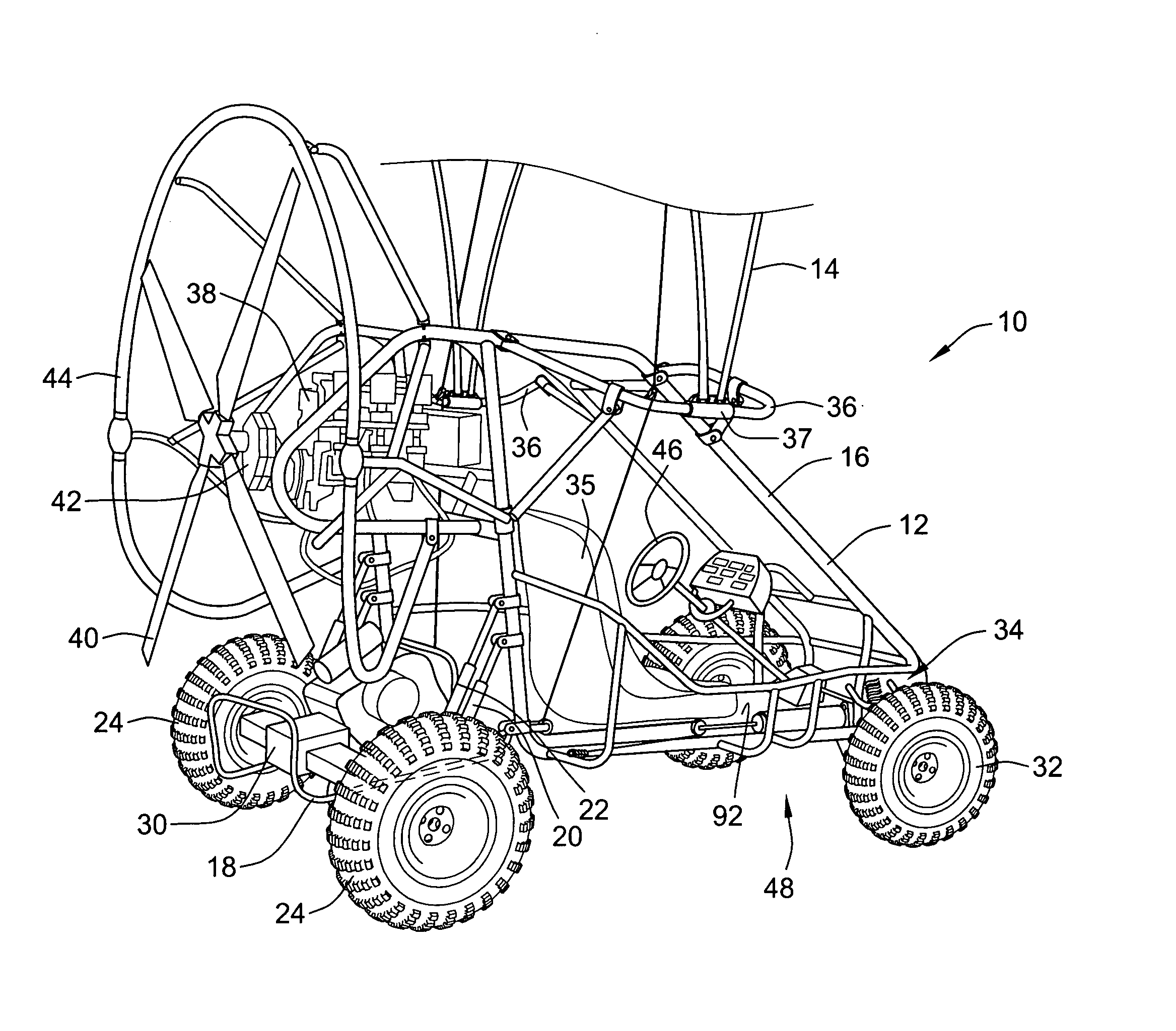
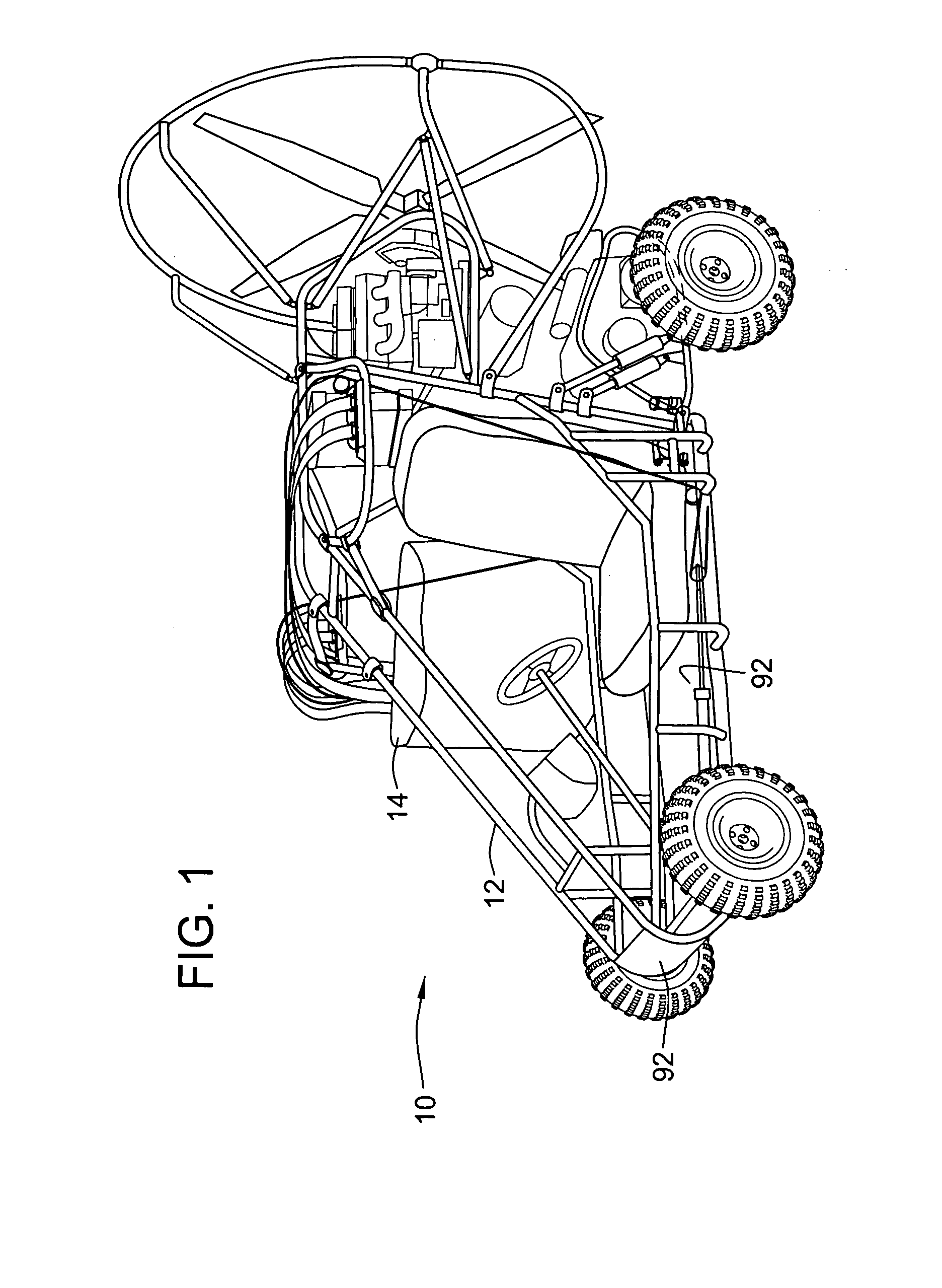
[0070] On the ground it is anticipated that a vehicle 10 according to the invention, the invention will normally be configured to travel over unimproved terrain at a maximum speed of 30 to 35 miles per hour as an ATV, while being powered with the ground propulsion apparatus, but the configuration of the vehicle 10 allows safe operation on the ground at significantly higher speeds. As a flying vehicle, the airspeed will be around 35 to 40 mph. Those skilled in the art will also recognize that the vehicle 10 can be propelled on the ground with the propeller 40 driven by the aircraft engine 38. Although this could not be done on a roadway where propeller-driven operation is prohibited, on flat level terrain, the vehicle 10 can be propelled by the propeller 40 and aircraft engine 38, and has been shown to be highly controllable at speeds up to 70 miles per hour, by virtue of the construction of the vehicle 10. Attempts to operate prior powered parachutes on the ground as ATVs have typic...

second embodiment

[0071]FIGS. 9-15 show a second exemplary embodiment of a vehicle 100, according to the invention, in the form of a flying ATV of a larger size providing significantly more ground clearance, higher operating speeds both on the ground and in the air, and more cargo carrying capability than the first exemplary embodiment of the invention described above in relation to FIGS. 1-8. Many aspects and features of the flying ATV 100 bear substantial similarity to the aspects and features described above in relation to the first exemplary embodiment of the flying ATV 10.

[0072] As shown in FIGS. 9 and 10, the vehicle 100 includes a chassis 102 and a parachute 104 operatively attached to the chassis 102 by outriggers 106, in a manner similar to that described above for attaching the parachute to the chassis in the first exemplary embodiment of the invention described above. In FIG. 9, the parachute 104 is illustrated in a deployed position. In FIG. 10, the parachute is illustrated as packed insi...


PUM


Abstract

A method and apparatus are provided for constructing, operating, and marketing a vehicle that is alternatively adaptable for controlled, powered operation on the ground as an all-terrain vehicle (ATV), or in the air as a powered parachute, or for controlled, powered operation on both the ground and in the air as a flying ATV. On the ground, the vehicle is configured for controlled, powered operation over both smooth and rough terrain, as a true all-terrain vehicle.

Description

CROSS-REFERENCE TO RELATED PATENT APPLICATIONS [0001] This patent application claims the benefit of U.S. Provisional Application No. 60 / 603,974, filed Aug. 24, 2004, the disclosure of which is incorporated herein by reference in its entirety.FIELD OF THE INVENTION [0002] This invention relates to vehicles that are capable of powered operation on the ground and in the air, and more specifically to a vehicle that is capable of operation alternatively on the ground, in the air, or both on the ground and in the air. BACKGROUND OF THE INVENTION [0003] It has long been desired to have a vehicle that is capable of controlled powered operation both on the ground and in the air. It has been particularly desirable to have an all-terrain vehicle (ATV) that can be either flown or driven to and from a remote location, over smooth or rough terrain, for operation on either the ground or in the air after reaching the remote location. For such operation, a flying ATV must be capable of taking off an...

Claims


Application Information

Patent Timeline
IPC IPC(8): B64C37/02
CPCB60F5/02B62K5/01B64C37/00B64C31/036B62K13/00
Inventor HOWARD, KENNETH D.
Owner HOWARD KENNETH D
Why Eureka
Try Eureka