
Travel assistance device for vehicle

a technology for assistance devices and vehicles, applied in navigation instruments, instruments, transportation and packaging, etc., can solve the problems of affecting and requiring a long time for processing image data, so as to shorten the processing time of image data picked up and improve the accuracy of obstacle recognition

Inactive Publication Date: 2007-01-25
MAZDA MOTOR CORP
View PDF1 Cites 22 Cited by
  • Summary
  • Abstract
  • Description
  • Claims
  • Application Information

AI Technical Summary

Benefits of technology

[0004] The present invention has been devised in view of the above-described problem, and an object of the present invention is to provide a travel assistance device for a vehicle that can properly shorten a processing time of image data picked up by the camera and improve accuracy of the recognition of obstacles.
[0006] According to the present invention, since a specified vehicle is identified among others on the basis of the vehicle's characteristics estimated with the data with respect to the feature of other vehicles obtained through the communication between vehicles and the position relationship between the traveling vehicle and other vehicles, it may be unnecessary that the traveling vehicle in advance prepares for some data base with respect to surrounding vehicles and then compares such data base to the image picked up for identifying the specified vehicle among others, so a time for processing the image can be shortened properly. Also, since detailed data with respect to the feature of the surrounding vehicles can be obtained through the communication between vehicles, an accurate detection of the surrounding vehicles can be provided.
[0007] According to an embodiment of the present invention, there is further provided an image-area restricting device operative to restrict an area of the image for identification by the vehicle identifying device on the basis of the position relationship determined by the position relationship determining device. Thereby, since the area of the image for the identification is restricted on the basis of the position relationship between the traveling vehicle and other surrounding vehicles, the image area to be processed can be narrowed and thereby the processing time can be shorted properly.
[0008] According to another embodiment of the present invention, there is further provided a vehicle-crash possibility estimating device operative to estimate a possibility of a crash between the traveling vehicle and the vehicle specified by the vehicle identifying device. Thereby, since the possibility of the crash with the specified vehicle identified in the image is estimated, an accurate prediction of the crash with surrounding vehicles can be provided.
[0009] According to another embodiment of the present invention, the vehicle-crash possibility estimating device is configured to estimate the possibility of the crash on the basis of respective histories with respect to a traveling speed and a traveling direction of the traveling vehicle and the vehicle specified by the vehicle identifying device. Thereby, since the possibility of the crash is estimated on the basis of the respective histories with respect to the traveling speed and direction of the traveling vehicle and other surrounding vehicles, the accuracy of the crash prediction can be further improved by predicting traveling paths of the traveling vehicle and other surrounding vehicles.
[0010] According to another embodiment of the present invention, the vehicle-crash possibility estimating device is configured to also estimate a hitting portion and angle at the crash, and there is provided a passenger protection device to operate on the basis of the hitting portion and angle estimated by the vehicle-crash possibility estimating device so as to protect a passenger of the traveling vehicle. Thereby, since the hitting portion and angle at the crash are also estimated and the passenger is protected according to these estimated portion and angle, a proper operation of the passenger protection device can be provided.

Problems solved by technology

Herein, there is a certain problem.
Accordingly, in a case where such data base contains lots of information, processing image data would require a long time.
Meanwhile, in a case where information of data base is too few, accuracy of recognition of obstacles would deteriorate.

Method used


Image

  • Travel assistance device for vehicle
  • Travel assistance device for vehicle
  • Travel assistance device for vehicle

Examples


Embodiment Construction

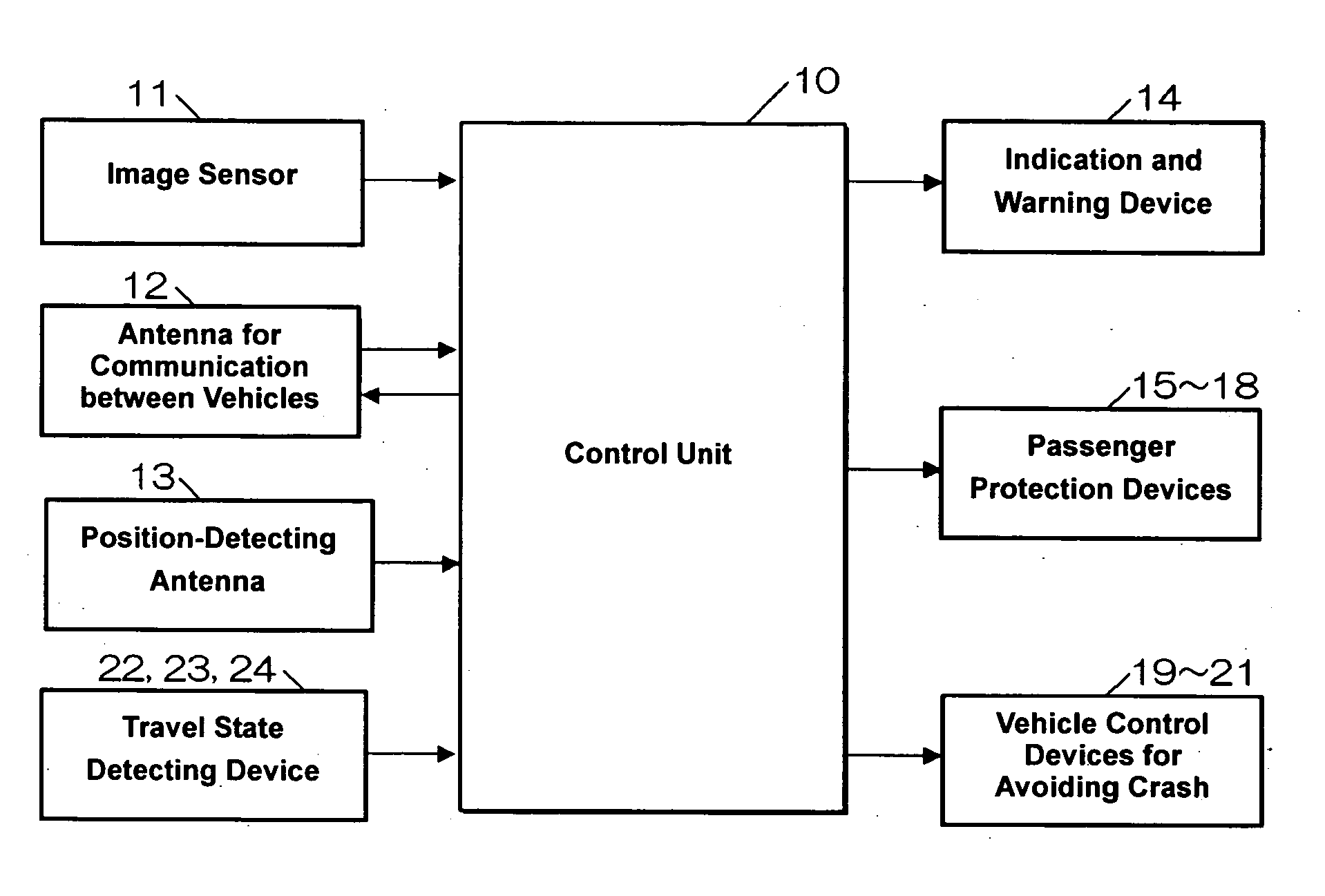
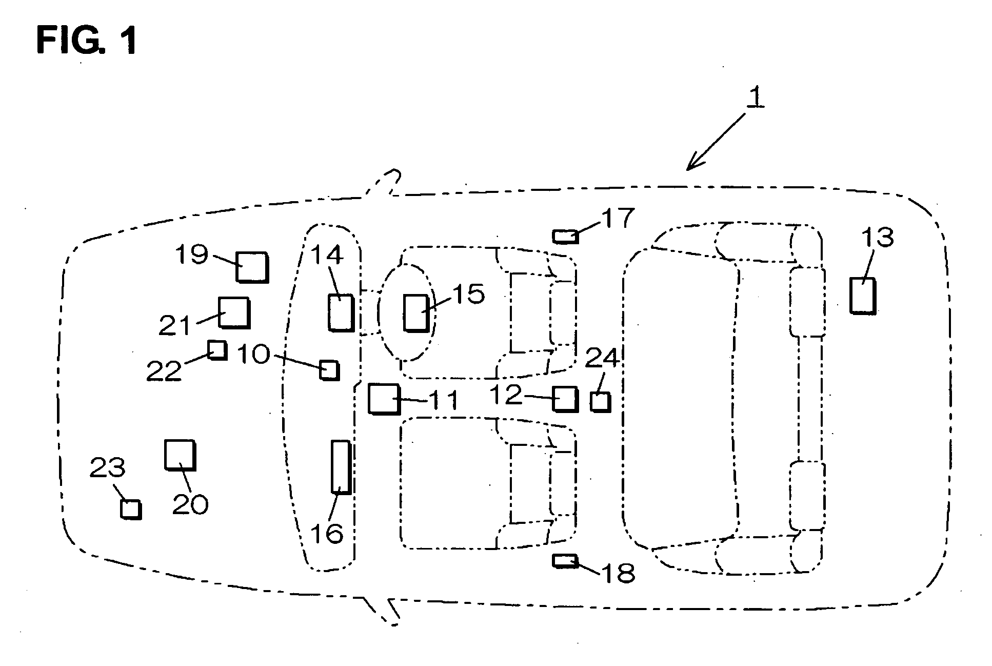
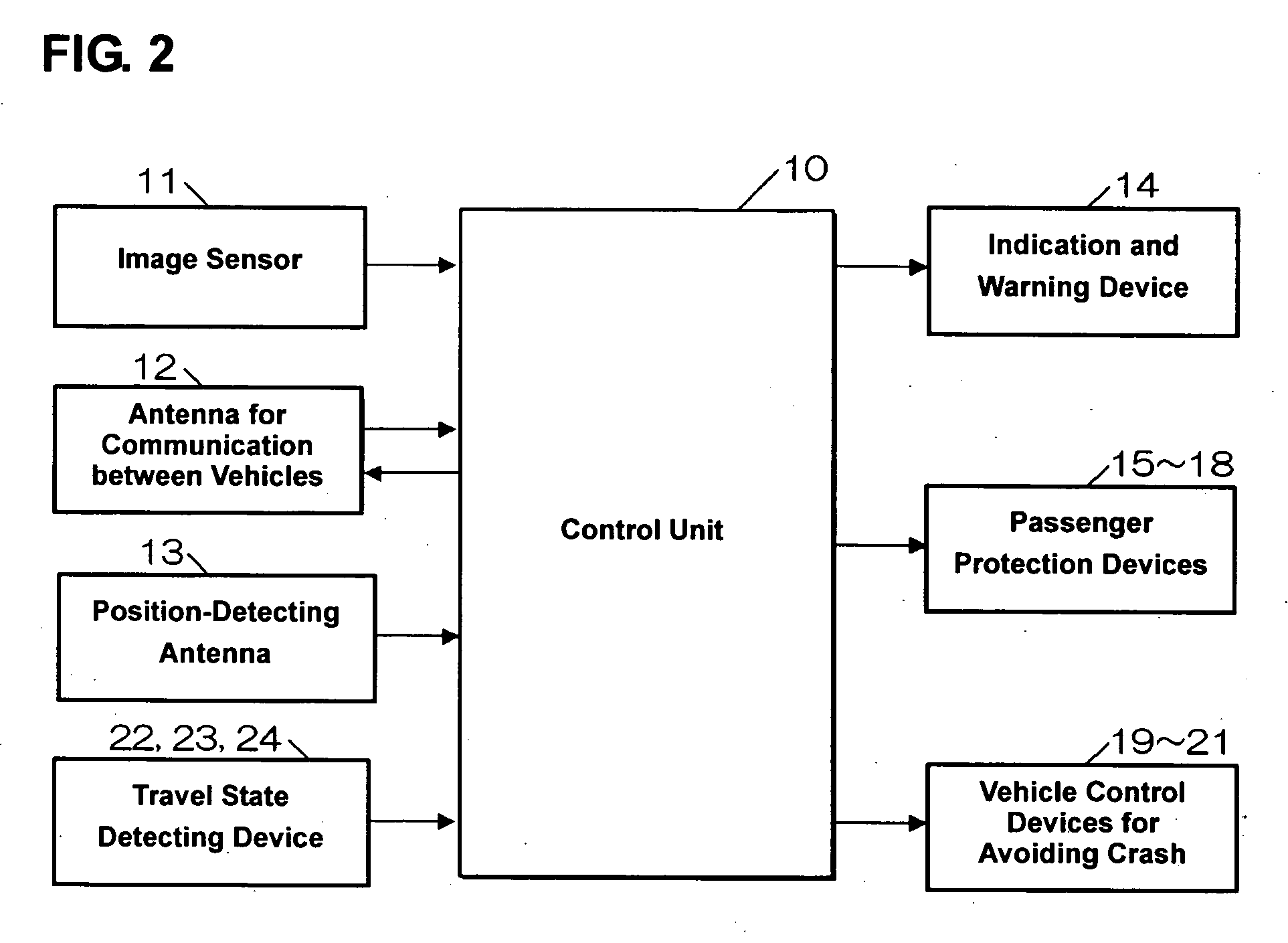
[0023] Hereinafter, a preferred embodiment of the present invention will be described referring to the accompanying drawings. FIG. 1 is a layout diagram of parts of a vehicle assistance device for a vehicle 1 according to the present embodiment. The vehicle assistance device 1 comprises a camera 11, such as a CCD camera or a CMOS camera, that is provided near a room mirror. The camera 11 picks up an image of surroundings of a traveling vehicle to identify obstacles from image data.

[0024] Also, the vehicle assistance device 1 comprises an antenna 12 for communication between vehicles as a signal receiving device that is provided at an upper portion, for example, a roof portion. This antenna 12 receives or sends signals from or to other vehicles that exit around the traveling vehicle through communication between vehicles. Herein, the signals sent from the surrounding vehicles contain vehicle information with respect to vehicle's position, model kind, size, feature, body color and so...


PUM


Abstract

The relative position of the surrounding vehicle to the traveling vehicle is determined from respective position information of the traveling vehicle and the surrounding-vehicle obtained through communication between vehicles. The processing area of the image picked up by the camera is restricted on the basis of this relative position. By comparing the template that is obtained with a scale-transfer from the previously-memorized template on the basis of the position information of the vehicle to the image of the vehicle with an image matching, the precious position of the surrounding vehicle is detected. Thereby, the passenger protection devices are operated. Accordingly, the processing time of image data picked up by the camera can be properly shortened and the accuracy of recognition of obstacles can be improved.

Description

BACKGROUND OF THE INVENTION [0001] The present invention relates to a travel assistance device for a vehicle that can properly assist recognition, judgment and operation of a driver by detecting surrounding obstacles and thereby reduce troubles in a vehicle traveling. [0002] Conventionally, a travel assistance device for a vehicle is known, which can assist driver's recognition, judgment and operation so as to avoid crashes with any obstacles, such as other vehicles, existing in surroundings of the traveling vehicle, by using communication between vehicles and a camera, such as CCD camera or CMOS camera, to pick up images and detect such obstacles. For example, Japanese Patent Application Laid-Open Nos. 2001-283381 or 2000-68923 disclose a technology in which existing obstacles on a traveling road can be recognized on the basis of image data of surroundings picked up by the camera of the traveling vehicle and information obtained through communication between vehicles. Also, Japanes...

Claims


Application Information

Patent Timeline
Patent Type & Authority Applications(United States)
IPC IPC(8): G01C21/00
CPCG08G1/161B60W2550/408B60W2556/65
Inventor KAWAMATA, SHIYOUTAKORE, HARUHISA
Owner MAZDA MOTOR CORP
Learn More