
Fusion imaging using gamma or x-ray cameras and a photographic-camera

a technology of fusion imaging and gamma or x-ray, which is applied in the field of diagnostic imaging, can solve the problems of difficult feature extraction methods such as intensity thresholding or edge detection, complicated registration process, and difficulty in accurately modeling the intensity relationship between the scans and subsequently aligning them

Inactive Publication Date: 2007-01-25
ZUCKIER LIONEL S
View PDF2 Cites 9 Cited by
  • Summary
  • Abstract
  • Description
  • Claims
  • Application Information

AI Technical Summary

Benefits of technology

[0016] The invention concerns having a fixed geometric relationship (e.g. a fixed position and orientation) between a visual photographic camera and another imaging or treatment source (herein also called a “camera”) such as a standard gamma-camera or an x-ray source. The fixed geometric relationship facilitates combining the visual, scintigraphic and / or x-ray data using affine transformations of the images from the varied sources.
[0020] Imaging of a ‘phantom’ physically combines several areas of visual and scintigraphic signal and takes advantage of the fixed geometric relationship between the cameras. This will allow the visual and scintigraphic images to be mapped to accurately superimpose the images.

Problems solved by technology

The feature that makes multiple scans useful, namely that they see the same source differently, complicates the registration process.
As each modality images tissue differently and has its own artifacts, accurately modeling the intensity relationship between the scans, and subsequently aligning them, is difficult.
Where the problem has been the patient being in different positions in the scanning devices used to image the anatomy the type of mathematical transformations has been mainly a rigid rotation of one image into another.
In general, methods of feature extraction such as intensity thresholding or edge detection do not work well on medical scans.

Method used


Image

  • Fusion imaging using gamma or x-ray cameras and a photographic-camera
  • Fusion imaging using gamma or x-ray cameras and a photographic-camera
  • Fusion imaging using gamma or x-ray cameras and a photographic-camera

Examples


Embodiment Construction

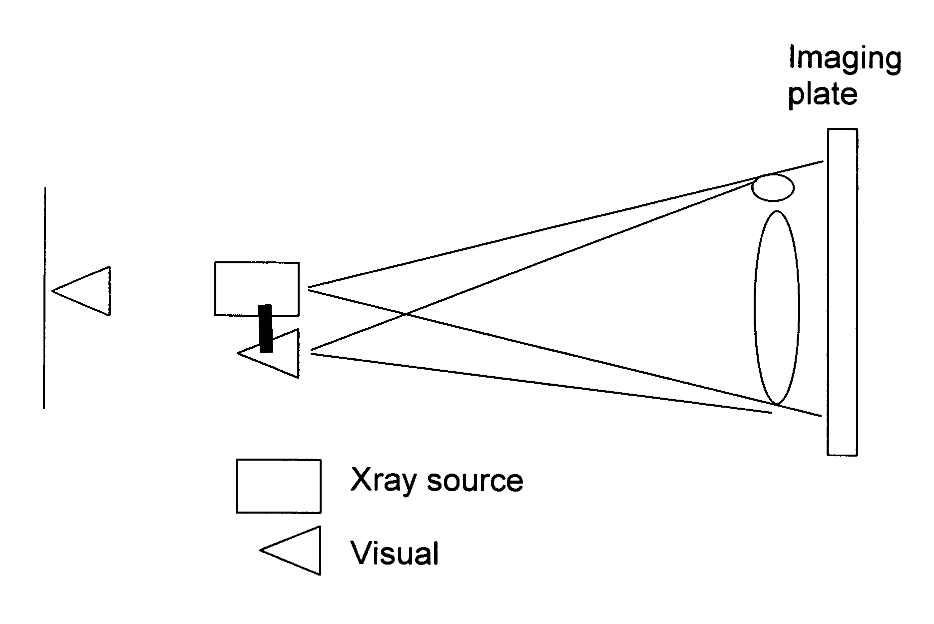
[0026] The invention comprises combining a visual photographic camera with another imaging or treatment source such as a standard gamma-camera (e.g. a scintigraphic camera or Anger camera) or an x-ray source in a fixed geometric relationship that facilitates combining the visual, scintigraphic and / or x-ray data using affine transformations of the images from the varied sources. The fixed geometric relationship allows the combination of clear visible images with those nuclear medicine images that display few anatomic references.

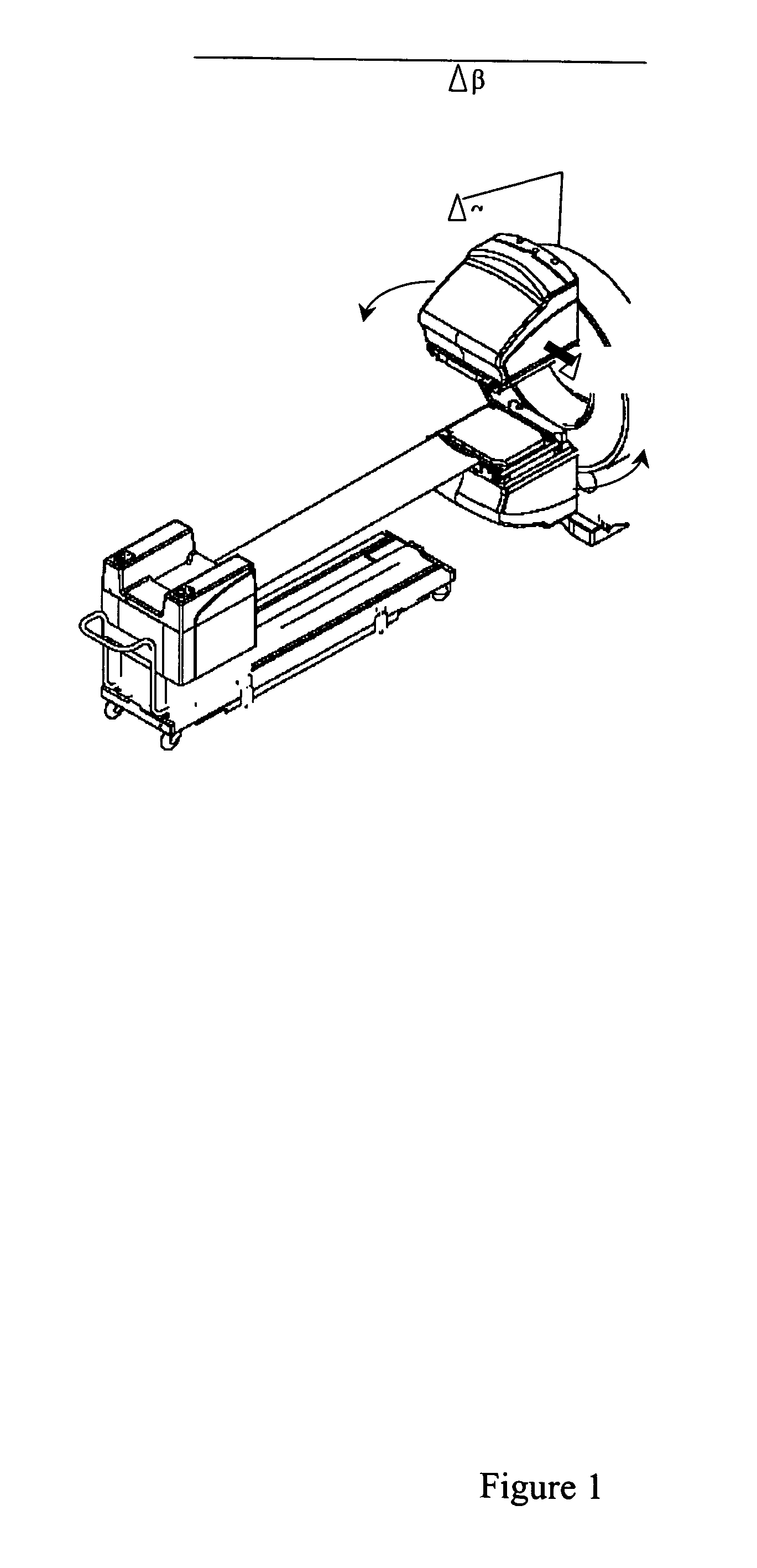
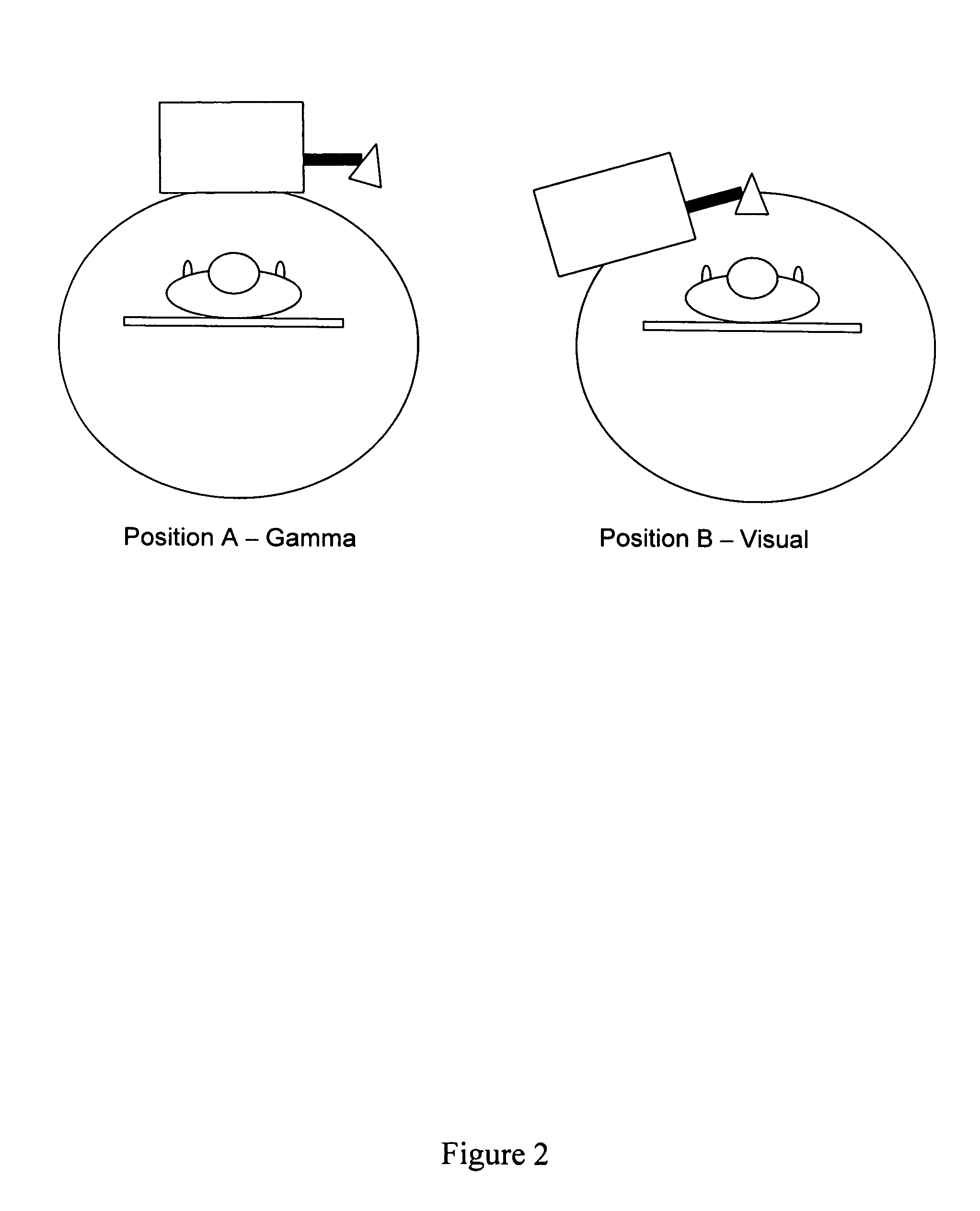
[0027] The visual camera is preferably a digital camera that can be remotely operated from the user's console. This camera can either be attached to the gamma camera gantry (position a), the gamma camera head (position y) or mounted on a structure such as the ceiling in the imaging room (positionβ). After the standard gamma camera image is obtained, the gamma-camera head can rotate either bringing the visual camera over the patient (FIG. 2), or moving out of ...


PUM


Abstract

A visual photographic camera is utilized in a fixed geometric relationship together with another imaging or treatment source such as a standard gamma-camera or an x-ray source. The visual camera is either attached to the gamma camera gantry, the gamma camera head or mounted on a structure such as the ceiling in the imaging room. After the standard gamma camera image is obtained, the gamma-camera head can rotate either bringing the visual camera over the patient, or moving out of the way to expose the patient to the field of view of the gantry-mounted or ceiling mounted camera. On the fusion image, both the visual and scintigraphic parameters for each specific location on the patient's body may be coded in a display. The visual camera may be utilized together with x-ray imaging equipment. In that application, the visual camera could either be attached to the x-ray tube assembly, or be mounted on a structure in the imaging room. Based on a fixed relationship between the location of the x-ray machine and the photographic camera, the two images could be scaled and superimposed to generate a ‘fusion’ image.

Description

[0001] This application claims the benefit of U.S. provisional application 60 / 584,510 filed Jan. 6, 2004.FIELD OF THE INVENTION [0002] This application relates to the art of diagnostic imaging. In particular it relates to simultaneous gamma-camera and photographic-camera imaging of a patient. BACKGROUND OF THE INVENTION [0003] Medical image analysis often involves the fusion, or image registration of images produced by different imaging sources. Registration is the process of aligning data into one consistent coordinate frame, particularly where tissues appear with different resolution in different types of imaging methods. Another situation is where a therapeutic source of radiation is used which does not present clear anatomic references and use of the source is supplemented by an alternative more clearly visible source in order to determine the placement of the therapeutic source. When acquired, multiple scans of the same patient will generally be unregistered, as the patient may...

Claims


Application Information

Patent Timeline
IPC IPC(8): G01N23/04
CPCG01N23/04
Inventor ZUCKIER, LIONEL S.
Owner ZUCKIER LIONEL S
Learn More