
Wide-band antenna, and wide-band antenna mounting substrate

a technology for antennas and substrates, applied in the direction of resonant antennas, substantially flat resonant elements, elongated active elements, etc., can solve the problems of limited space for electronic parts to be mounted on the ground pattern b>63/b>, large antenna in its entirety, etc., to achieve wide space for electronic parts, reduce the effect of size and widen the band of vswr

Inactive Publication Date: 2007-01-18
ORMON CORP
View PDF11 Cites 5 Cited by
  • Summary
  • Abstract
  • Description
  • Claims
  • Application Information

AI Technical Summary

Benefits of technology

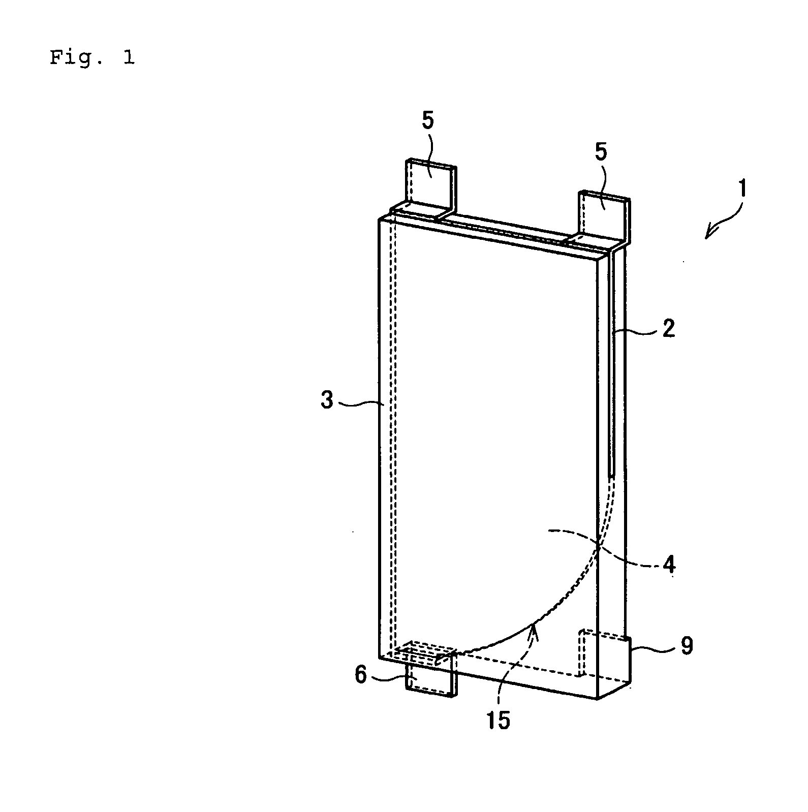
[0011] The present invention has been conceived in view of the problems described above, and has an object to provide an antenna, which can be reduced in size and which can widen the band of a VSWR without changing the shape of a ground pattern (or a grounding electrode) but while retaining a wide space for electronic parts to be mounted, and a wide-band antenna mounting substrate.
[0042] Therefore, the invention has an advantage to provide the antenna, which can be reduced in size and which can widen the band of the VSWR without changing the shape of the ground pattern (or the grounding electrode) but while retaining the wide space for electronic parts to be mounted.

Problems solved by technology

Therefore, the antenna has a problem that it is large in its entirety.
This causes a problem of troubles.
Moreover, the ground pattern 63 has a tapered shape thereby to cause a problem that the space for the electronic parts to be mounted on the ground pattern 63 is limited.

Method used


Image

  • Wide-band antenna, and wide-band antenna mounting substrate
  • Wide-band antenna, and wide-band antenna mounting substrate
  • Wide-band antenna, and wide-band antenna mounting substrate

Examples


embodiment

Mode 3 of Embodiment

[0104] An antenna of still another mode of embodiment is described. For convenience of description, the members having functions similar to those of the members described in the modes 1 and 2 of embodiment are omitted in their description by designating them by the common reference numerals.

[0105] In both the aforementioned modes of embodiment, the feeding conductor 2 is clamped in the dielectric substrate 3. However, the constitution should not be limited to those modes, but the feeding conductor 2 may also be disposed on the surface of a dielectric substrate (a supporting member) 21, as shown in FIG. 11. Here, the supporting member is exemplified by the dielectric substrate 21. In this mode of embodiment, however, the supporting member need not have the dielectric property, but may be any if it can support the feeding electrode portion 4 of the feeding conductor 2. However, the dielectric substrate 21 is preferably made of a dielectric resin. If the dielectric...


PUM


Abstract

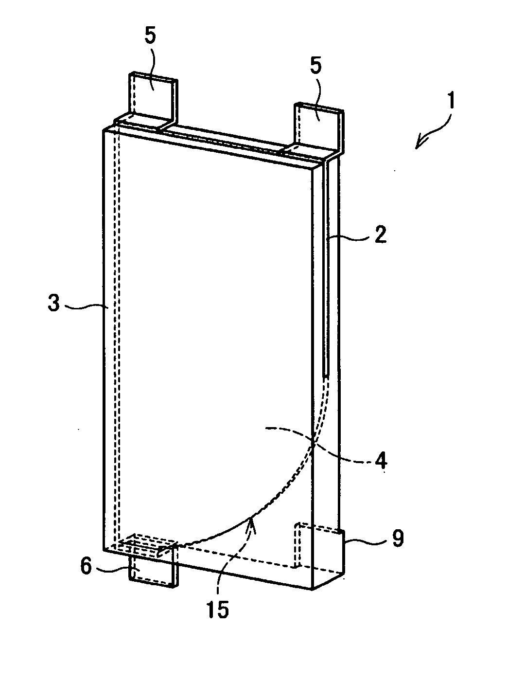
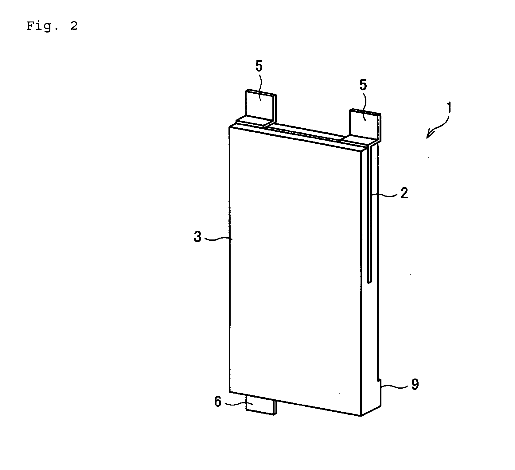
An antenna which can be reduced in size and which can widen the band of a VSWR without changing the shape of a ground pattern but while retaining a wide space for electronic parts to be mounted. The antenna 1 has a feeding electrode portion 4. This feeding electrode portion 4 includes a conductive flat plate, which is cut away at its one corner of a rectangle such that the cut-away portion 15 is defined by an arc joining two sides making a corner and bulging inward.

Description

BACKGROUND OF THE INVENTION [0001] 1. Field of the Invention [0002] The present invention relates to a wide-band antenna for widening the band of VSWR characteristics, and to a wide-band mounting substrate. [0003] 2. Background Art [0004] In recent years, the radio communication systems become various and need antennas corresponding to various frequencies, and accordingly a wide-band antenna. In the wide-band antenna, as shown in FIG. 13, a radiative conductor 51 of a semicircular shape is so mounted on a substrate (a GND substrate) 50 having a ground pattern such that its arc center portion (a feeding terminal 52) contacts with the GND substrate 50. [0005] The distance between the radiative conductor 51 and the GND substrate 50 becomes the lager as the closer to the end of the GND substrate 50, so that the antenna can widen the band of VSWR (Voltage Standing Wave Ratio) characteristics. [0006] On the other hand, a radio communication card of the PC card type is used for the radio c...

Claims


Application Information

Patent Timeline
Patent Type & Authority Applications(United States)
IPC IPC(8): H01Q1/24
CPCH01Q1/243H01Q9/40H01Q9/0407
Inventor SHINKAI, TETSUO
Owner ORMON CORP
Learn More