Method and system for design and analysis of fastened joints

a fastener and design technology, applied in the field of methods and systems for designing and analyzing fasteners, can solve the problems of increasing and unnecessary costs, difficult to achieve a balance between adequacy and cost of fasteners, and time-consuming process of specifying and analyzing potential fasteners

Inactive Publication Date: 2007-01-11
CATERPILLAR INC
View PDF3 Cites 16 Cited by
  • Summary
  • Abstract
  • Description
  • Claims
  • Application Information

AI Technical Summary

Problems solved by technology

On the other hand, over-design of fasteners leads to increased and unnecessary costs.
Balancing adequacy of the fastened joints with costs is often difficult to achieve.
However, the process of specifying and analyzing potential fasteners can be time consuming and may not fully utilize the skills of an experienced engineer.
However, in the absence of an appropriate tool for fastener specification, analysts may not be capable of performing the associated tasks in place of an engineer.
Further, the lack of such a tool may result in a loss of uniformity within the design process regardless of whether an engineer or an analyst is responsible for the specification of fasteners.
The design process itself offers little in the way of a solution.
Typical computer-based design programs are isolated from other design programs, and thus produce inconsistent design choices of fastener requirements.
Design programs also tend to be broad in scope, and thus may not address the myriad of specific issues that arise with respect to fastener needs.
Further, design programs typically do not include functionality for analysis of a completed design, thereby requiring additional software and integration.
For example, it is limited to analysis of data values entered by a user and does not integrate with a computer aided drafting tool.
Further, it does not provide listings of potential fasteners, and the tool requires switching between numerous “function” pages, making it difficult to navigate.

Method used


Image

  • Method and system for design and analysis of fastened joints
  • Method and system for design and analysis of fastened joints
  • Method and system for design and analysis of fastened joints

Examples


Embodiment Construction

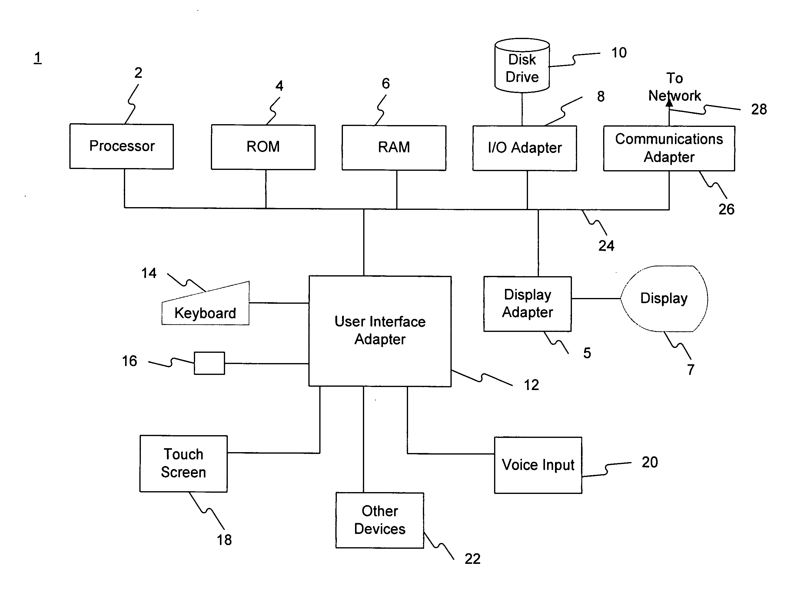
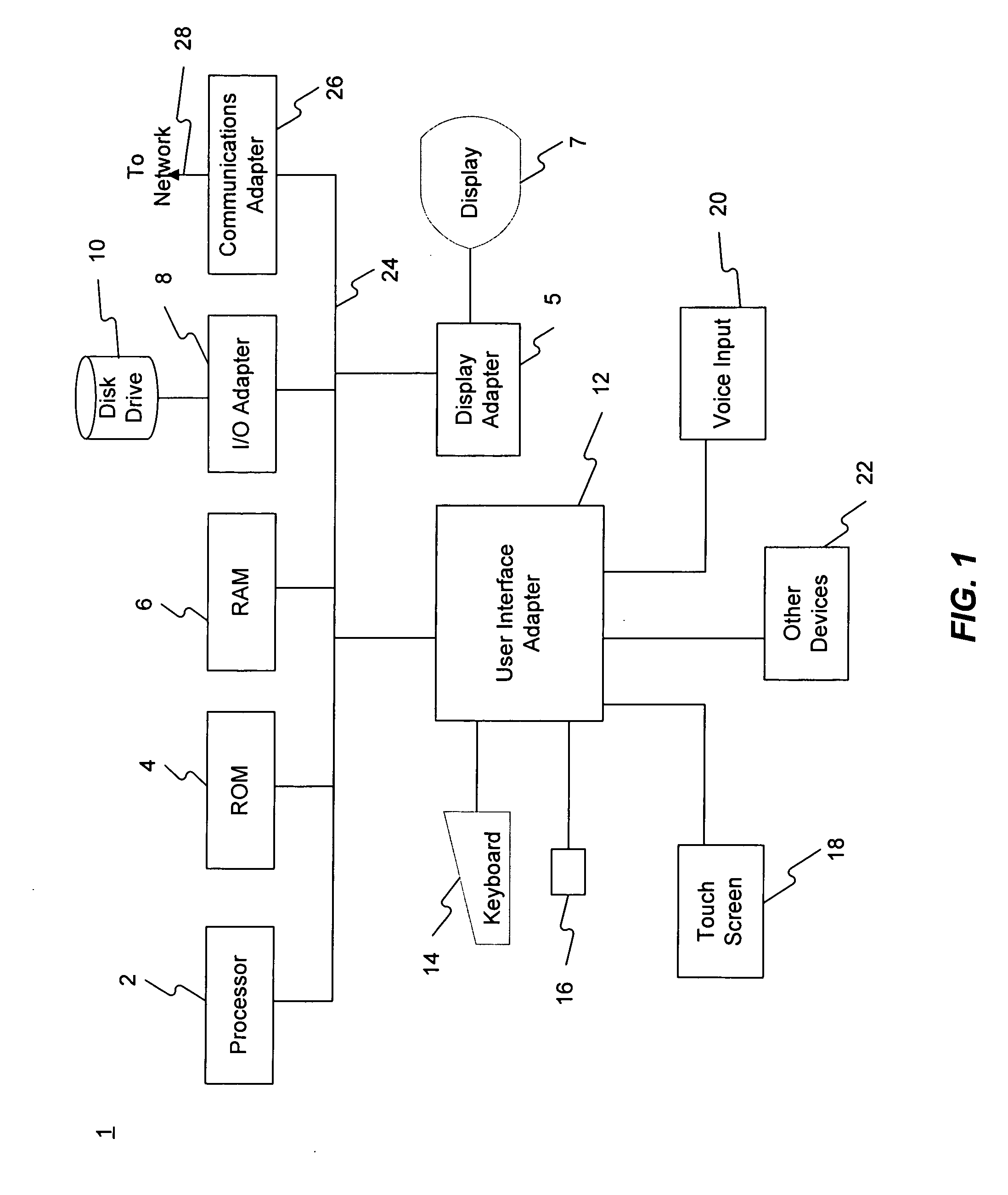
[0016]FIG. 1 is a block diagram of a host computer system 1 capable of implementing the methods and systems disclosed. Host computer system 1 may include a group of computer programs, program modules, and computer readable data stored on a computer readable media operating to cause computer system 1 to perform the actions described herein. Host computer system 1 may include a desktop or portable computer, a workstation, a server, a personal digital assistant, or any other computer system. Host computer system 1 may include a processor 2, a read-only memory (ROM) 4, a random access memory (RAM) 6, an input / output (I / O) adapter 8 for connecting peripheral devices such as disk drives 10, a user interface adapter 12 for connecting input devices such as a keyboard 14, a mouse 16, a touch screen 18, a voice input 20 and / or other devices 22 to a system bus 24. A communications adapter 26 may connect host computer system 1 to a network 28, and a display adapter 5 may connect system bus 24 t...


PUM


Abstract

A computer system for analyzing fasteners and fastened joints includes a display and a processor. The processor may be configured to provide a first interface and a second interface to the display, and receive, via the first or second interface, a set of parameters associated with a component to be fastened. Further, the processor may be configured to provide the set of parameters to an analysis tool, execute instructions associated with the analysis tool, and provide an output of the analysis tool to the display via either the first or second interface. The first interface may include at least one data entry form, and the second interface may be associated with a computer aided drafting tool.

Description

[0001] Applicants claim the right to priority under 35 U.S.C. §119(e) based on U.S. Provisional Patent Application No. 60 / 696,956, entitled “METHOD FOR DESIGN AND ANALYSIS OF FASTENED JOINTS,” filed Jul. 6, 2005 which is expressly incorporated herein by reference in its entirety.TECHNICAL FIELD [0002] This disclosure relates generally to methods and systems for designing and analyzing fastened joints, and more particularly, to methods and systems for designing and analyzing fasteners applied to joints. BACKGROUND [0003] Manufacturing and assembly processes frequently employ the use of fasteners, such as bolts, to fasten components together. It is imperative for the quality and useful life of the completed product that the fasteners be adequate for the job. For example, the engagement type of the joints, the environment that the joints and fasteners might be subjected to (such as corrosion), the condition of applied finishes (such as paint), geometrical constraints, design rules, and...

Claims


Application Information

Patent Timeline
Patent Type & Authority Applications(United States)
IPC IPC(8): G06F11/00
CPCG06F17/50G06F30/00
Inventor AHMAD, NAUSHEENHOLFELNER, BRIAN KARLWILLIAMS, O.W. JR.ROBISON, PAUL GAYLEN
Owner CATERPILLAR INC
Why Eureka
Try Eureka