
Power generating systems

a power generation system and power technology, applied in the direction of mechanical energy handling, dynamo-electric brake control, transportation and packaging, etc., can solve the problems of significant mechanical wear on all moving parts, reduce the efficiency of the power generation system, etc., and achieve the effect of reducing frictional wear and increasing outpu

Inactive Publication Date: 2007-01-11
CAMEL CLUB
View PDF98 Cites 36 Cited by
  • Summary
  • Abstract
  • Description
  • Claims
  • Application Information

AI Technical Summary

Benefits of technology

The system achieves increased output with reduced frictional wear and heat generation, enhancing efficiency and extending the lifespan of moving parts.

Problems solved by technology

However, due to frictional forces between the mechanical couplings heat is produced, thereby reducing the efficiency of the power generating systems.
In addition, the frictional forces cause significant mechanical wear on all moving parts.

Method used


Image

  • Power generating systems
  • Power generating systems
  • Power generating systems

Examples


Embodiment Construction

[0059] Reference will now be made in detail to the illustrated embodiments of the present invention, examples of which are illustrated in the accompanying drawings.

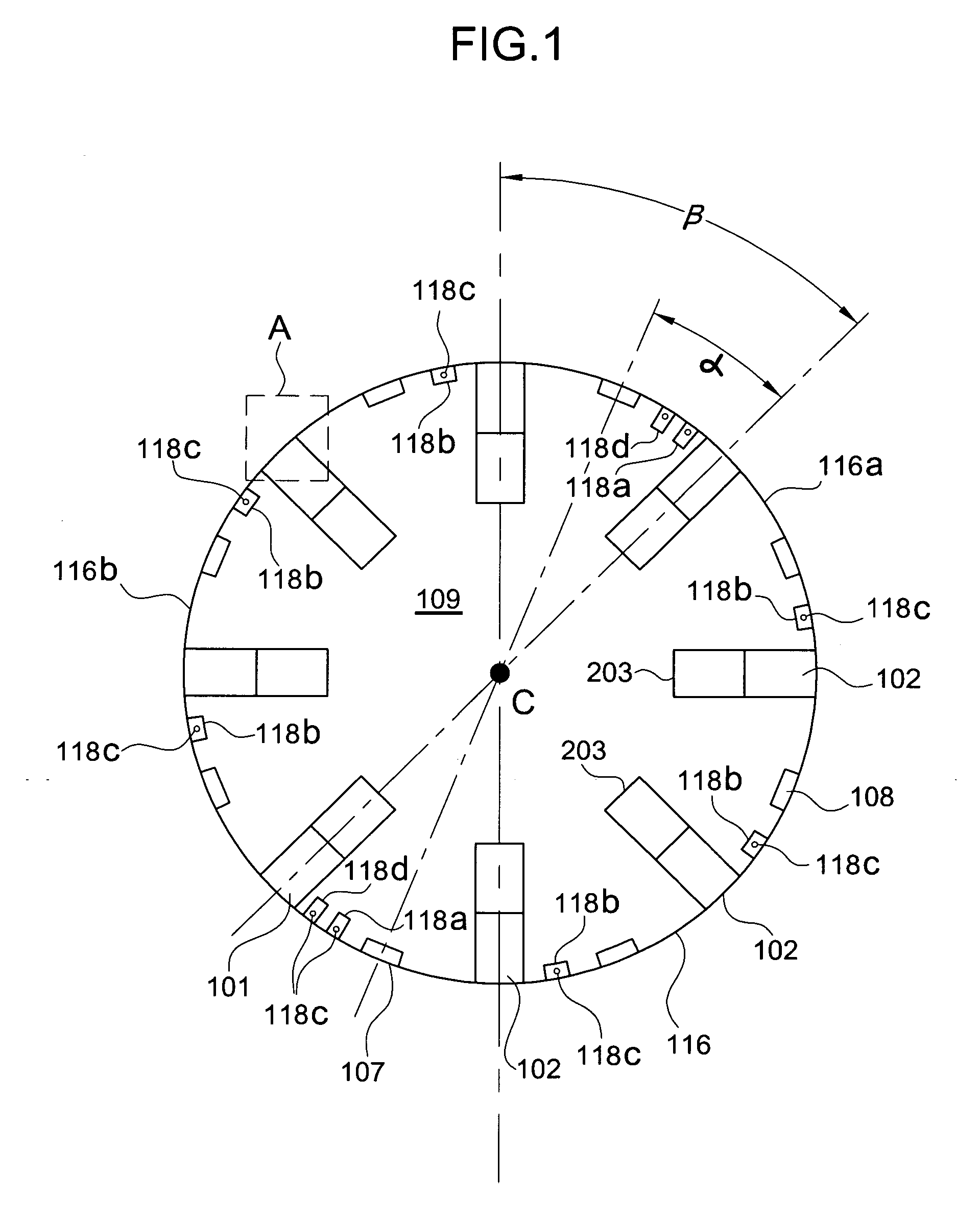
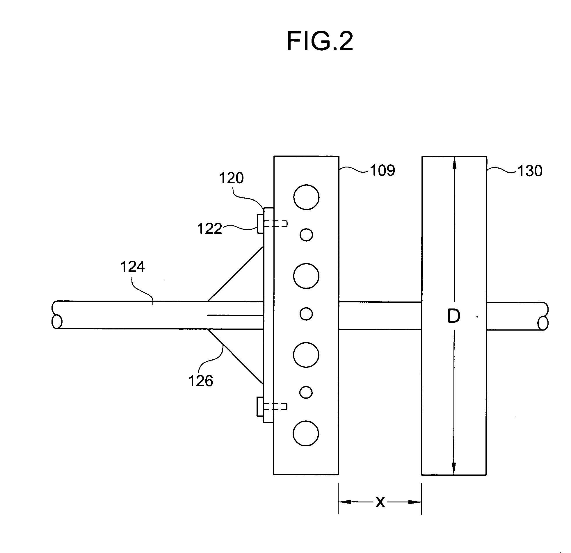
[0060]FIG. 1 is a layout diagram of an exemplary flywheel according to the present invention. In FIG. 1, a flywheel 109 may be formed from a cylindrical core of composite material(s), such as nylon, and may be banded along a circumferential edge of the flywheel by a non-magnetic retaining ring 116, such as non-magnetic stainless steel or phenolic materials. The flywheel 109 may include a plurality of magnets 102 disposed within a plurality of equally spaced first radial grooves 101 of the flywheel 109, wherein each of the magnets 102 may generate relatively strong magnetic fields. In addition, each of the magnets 102 may have cylindrical shapes and may be backed by a backing plate 203, such as soft iron or steel, disposed within each of the plurality of first radial grooves 101 in order to extend the polar fields of the ...


PUM


Abstract

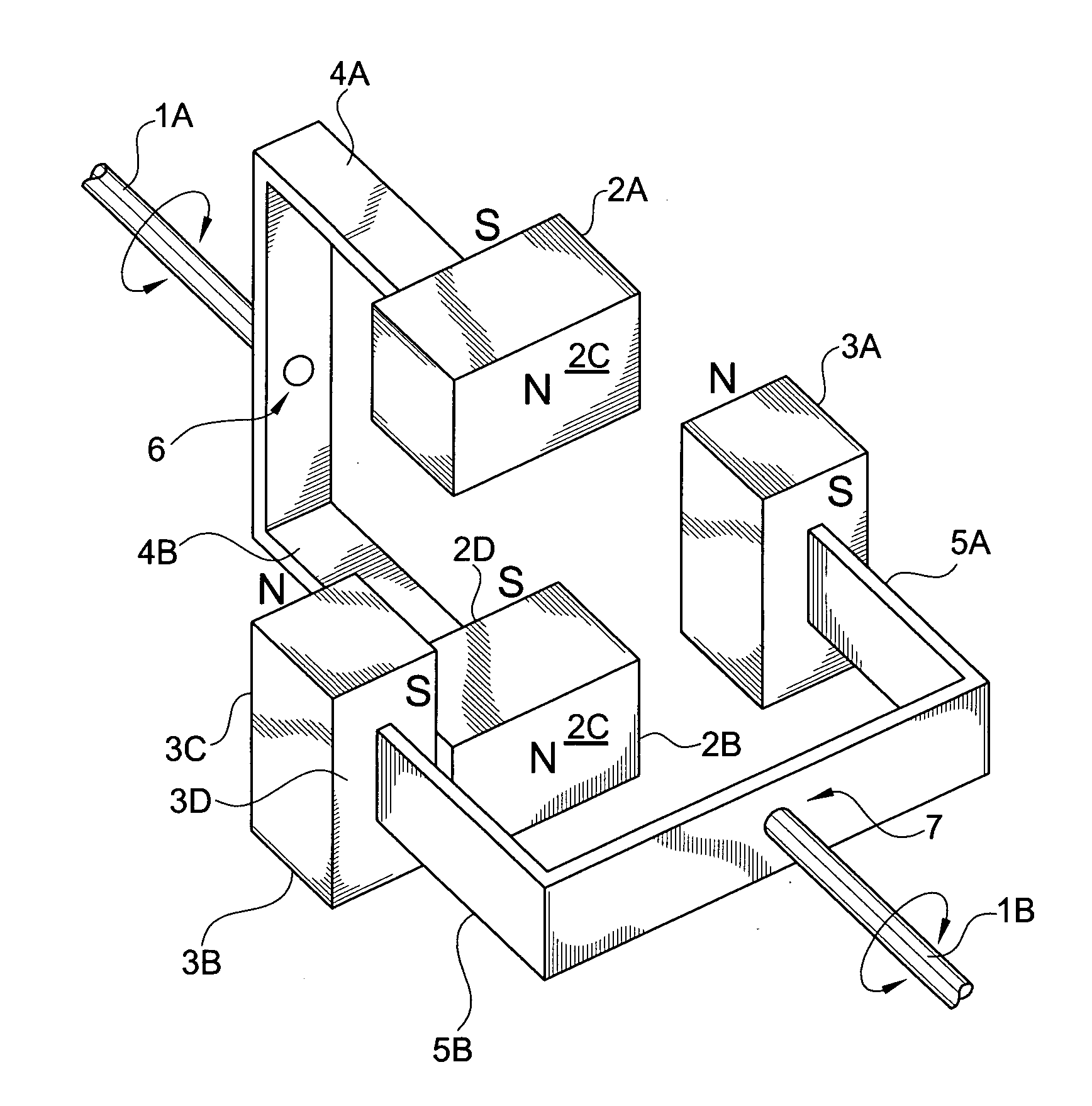
A power generating system includes a torque converter system receiving a rotational motion having a first torque from a source and producing a rotational output having a second torque different from the first torque, a transfer system having a first portion coupled to the rotational output of the torque converter system and a second portion magnetically coupled to the first portion, and a generator system coupled to the transfer system to produce and electrical output.

Description

[0001] The present application is a Continuation-In-Part of U.S. patent application Ser. No. 10 / 758,000 filed on Jan. 16, 2004, which claims priority to U.S. Provisional Patent Application No. 60 / 440,622 filed on Jan. 17, 2003, which is hereby incorporated by reference.BACKGROUND OF THE INVENTION [0002] 1. Field of the Invention [0003] The present invention relates to power generating systems. More specifically, the present invention relates to various power systems using torque converter and generator systems. [0004] 2. Discussion of the Related Art [0005] In general, power generation systems make use of mechanical couplings to transmit rotational motion between drive shafts. However, due to frictional forces between the mechanical couplings heat is produced, thereby reducing the efficiency of the power generating systems. In addition, the frictional forces cause significant mechanical wear on all moving parts. SUMMARY OF THE INVENTION [0006] Accordingly, the present invention is d...

Claims


Application Information

Patent Timeline
Patent Type & Authority Applications(United States)
IPC IPC(8): H02K7/06H02K49/00B60K17/12H02K7/02H02K49/10
CPCB60K17/12H02K7/025Y02T10/6204H02K49/108Y02E60/16H02K49/102Y02T10/62
Inventor WISE, RICHARD J.
Owner CAMEL CLUB
Learn More