
Mounting for a probe sensor

a technology of electronic sensors and mounting brackets, which is applied in the direction of screws, load-modifying fasteners, instruments, etc., can solve the problems of affecting the substantial compressive load of the insert member, and achieve the effect of reducing the overall cost and weight of the device, and ensuring the integrity of the devi

Inactive Publication Date: 2007-01-11
DELPHI TECH INC
View PDF22 Cites 10 Cited by
  • Summary
  • Abstract
  • Description
  • Claims
  • Application Information

AI Technical Summary

Benefits of technology

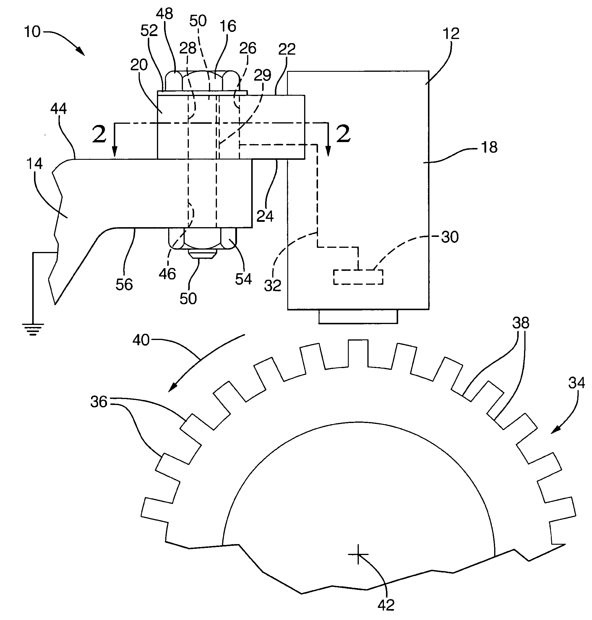
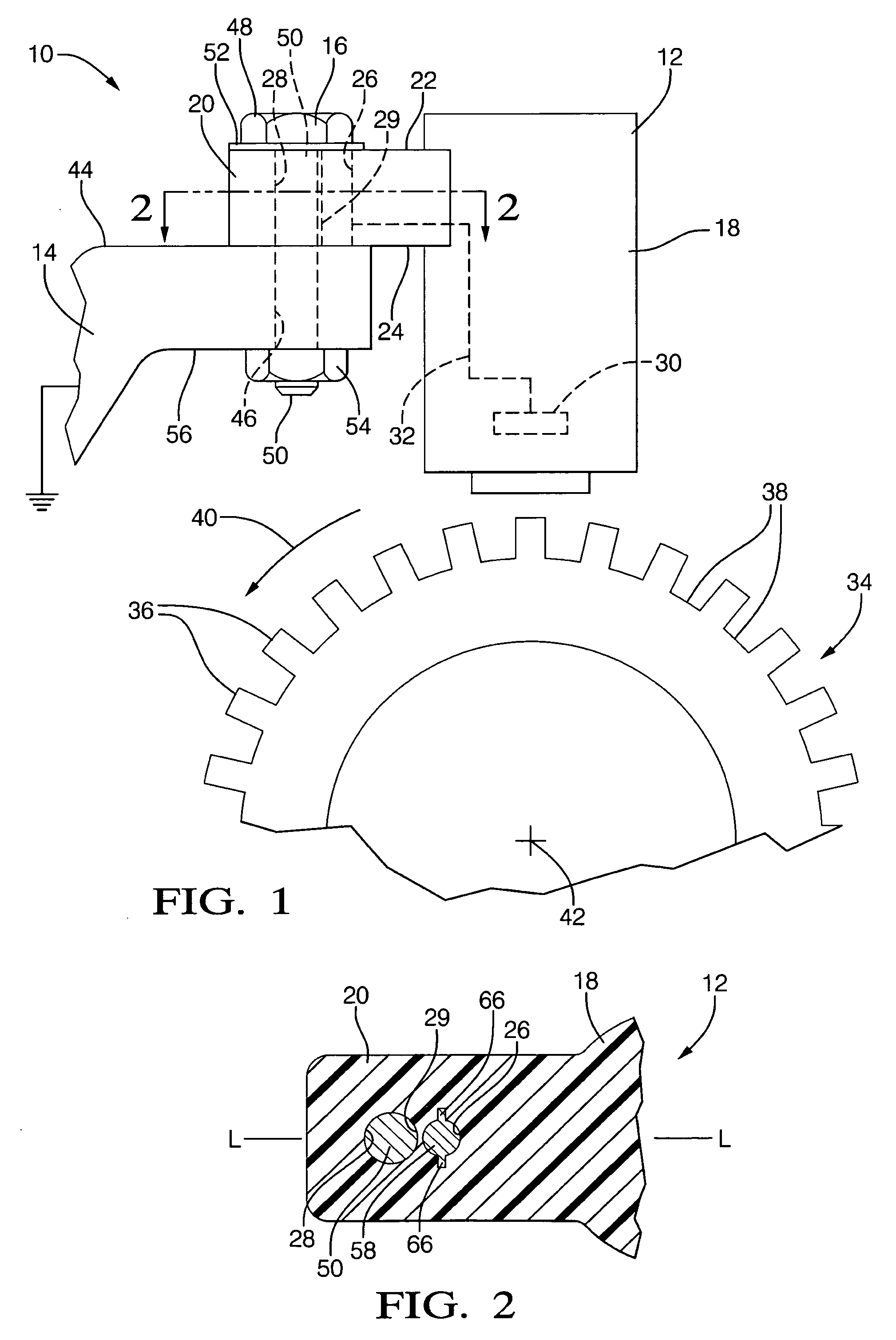
[0008] Generally, the present invention fulfills the forgoing needs by providing, in one aspect thereof, the combination of an electromechanical device, such as a probe sensor, with a fastener. The electromechanical device includes a body portion and a flange extending there from, wherein the flange defines opposed, generally parallel surfaces. First and second passages are formed within the flange, with each passage interconnecting the parallel surfaces. An insert member is disposed within the first passageway. Lastly, the fastener has a head portion which substantially overlays the first passageway and a shank portion which extends through the second passageway. In application, the shank portion serves to interconnect the head portion with a substantially fixed structure, such as the frame of a motor vehicle, and thereby affect substantial compressive loading on the insert member. This arrangement has the advantage of reducing overall cost and weight of the device while providing a more robust design.
[0009] According to an aspect of the invention, the insert member is formed of a material having a relatively high yield point, such as steel, while the body portion and flange are formed of base material having a relatively low yield point, such as polymeric material. This arrangement permits substantial weight and cost reduction of the sensor without degradation of overall performance and reliability.
[0010] According to another aspect of the invention, the first and second passageways extend normally to the parallel flange surfaces and are tangentially aligned. This arrangement has the advantage of facilitating mold forming of the body portion and flange using low cost tooling and processes.
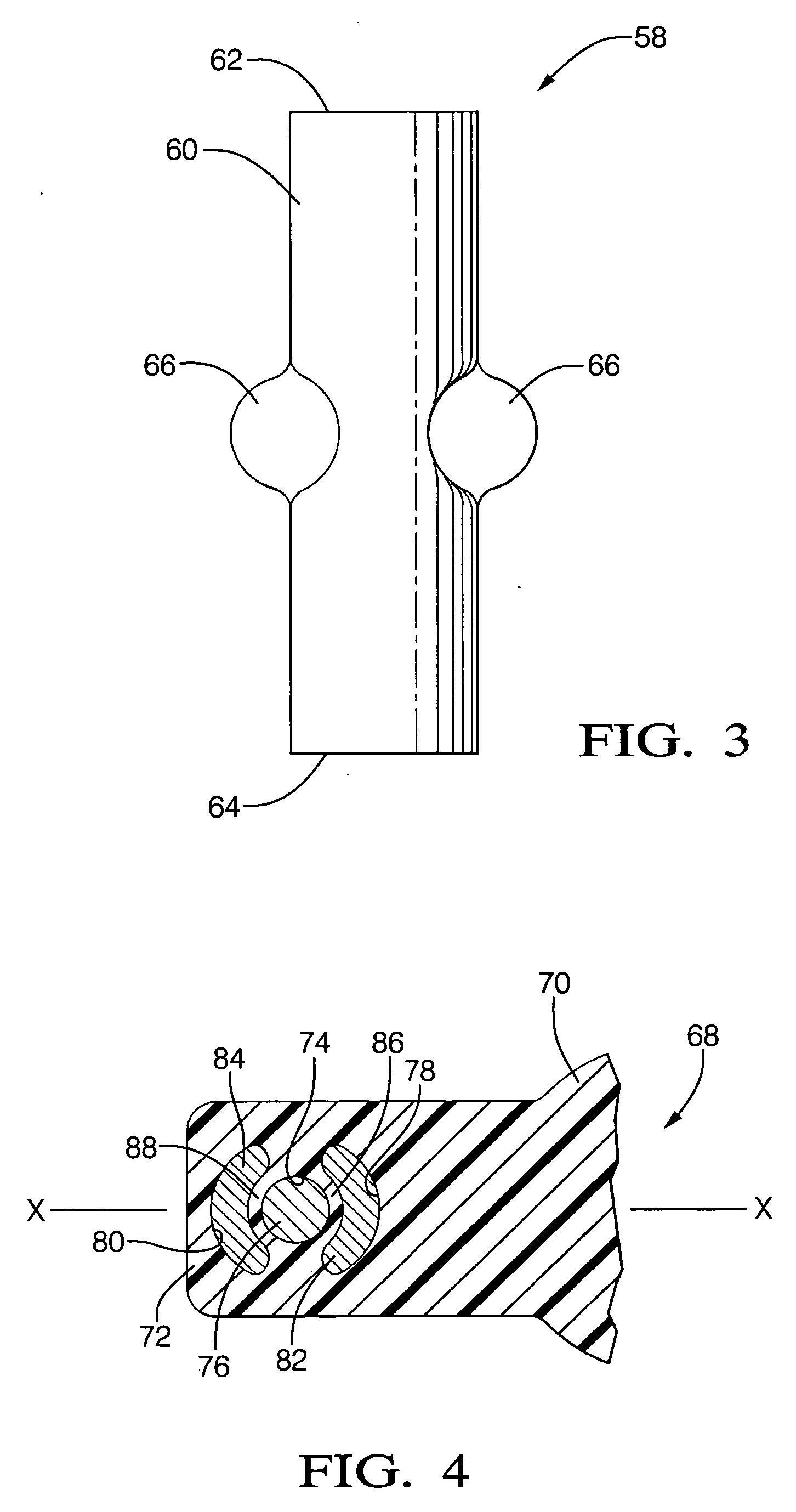
[0011] According to another aspect of the invention, the insert member is substantially cylindrical in shape and has one or more localized crimps formed therein to affect a regionalized increase in the nominal cross-sectional dimension in at least one direction generally parallel to the flange parallel surfaces. This feature has the advantage of using inexpensive bar stock to fabricate the insert members and ensures that the insert member remains in place after being press or interference fit within the first passageway.
[0012] According to yet another aspect of the invention, the insert member can be circumferentially elongated to provide greater composite yield strength without increasing the total amount of material employed in the insert member.
[0013] According to still another aspect of the invention, the first and second passageways are aligned on a line of elongation of the flange, which extends through the body portion of the electromechanical device. This arrangement has the advantage of minimizing the overall dimensions of the flange, which saves piece cost and enhances packaging flexibility of the overall system.

Problems solved by technology

In application, the shank portion serves to interconnect the head portion with a substantially fixed structure, such as the frame of a motor vehicle, and thereby affect substantial compressive loading on the insert member.

Method used


Image

  • Mounting for a probe sensor
  • Mounting for a probe sensor
  • Mounting for a probe sensor

Examples


Embodiment Construction

[0020] The present invention is intended for application in automotive vehicle systems and will be described in that context. It is to be understood, however, that the present invention could also be successfully applied in many other applications. Accordingly, the claims herein should not be deemed as limited to the specifics of the preferred application as described hereunder. The preferred application of the present invention involves the mounting of a probe type sensor as part of an automotive system and represents an extremely robust, low cost, compact design, which can be easily configured to accommodate application specific packaging requirements. Furthermore, the component configuration and arrangement enables use of simplified manufacturing processes and somewhat relaxed tolerances, increasing turnover and lowering cost without adversely impacting quality.

[0021] Referring to FIG. 1, a probe sensor assembly 10 is illustrated comprising a probe sensor 12 rigidly mounted to a...


PUM


Abstract

A robust, easy to mount probe sensor includes an elongated body enclosing a sensor element and an integral flange extending away from the body. The body and flange are formed of material having a relatively low characteristic yield point. First and second generally parallel closely spaced through passages extend through the flange. An insert formed of material having a relatively high characteristic yield point is disposed in one of the passages. A fastener including a shank portion which extends through the other passageway includes an enlarged head which overlays the insert containing passageway and engages an attachment structure to effect directed compressive loading of the probe sensor flange.

Description

TECHNICAL FIELD [0001] The present invention relates generally to the packaging and mounting of transducers within a host system such as a motor vehicle. More particularly, the present invention relates to the cantilevered mounting of probe type electronic sensors. BACKGROUND OF THE INVENTION [0002] Electronic sensors which are suitable for detecting discontinuities, such as gear teeth, along a target surface are well known and used in automotive applications such as brake systems, cruise control systems, transmission systems, as well as many others. In its environment of use, the sensor apparatus requires a support structure, a sensor housing and means for mounting the sensor housing onto the support structure. The stack-up of tolerances of the components comprising the sensor within the housing in addition to the stack-up of tolerances associated with connection to the mounting bracket for mounting the sensor housing onto the support structure contribute to the difficulty of estab...

Claims


Application Information

Patent Timeline
Patent Type & Authority Applications(United States)
IPC IPC(8): F16B31/02
CPCG01P1/00G01D5/147Y10S248/904G01P1/026
Inventor PADDOCK, STEPHEN G.BARRERA, LEONEL A.
Owner DELPHI TECH INC
Learn More