
Heat sink structure for air mattress

a technology of air mattress and heat sink, which is applied in the direction of fluid mattresses, domestic cooling devices, sofas, etc., can solve the problems of exhausting air taking heat and damp away, unable to be too big, and unable to cool down

Inactive Publication Date: 2007-01-11
APEX MEDICAL CORPORATION
View PDF0 Cites 5 Cited by
  • Summary
  • Abstract
  • Description
  • Claims
  • Application Information

AI Technical Summary

Benefits of technology

[0007] The primary objective of the present invention is to provide a heat sink structure for air mattress to drain out the inside air, and then the air takes some heat and damp away to make the air mattress more dry and comfortable.
[0008] Another objective of the present invention is to provide a heat sink structure for air mattress that reclaim the air exhausted from airbags for dropping in temperature, and the air takes some heat and damp away to make the air mattress more dry and comfortable.

Problems solved by technology

Usually, these apertures of the airbags are produced with laser processing, and these apertures cannot be too big otherwise the airbags cannot be pumped up.
On the other hand, if the apertures are too small, it is insufficient to cool down and to exsiccate while the airbags cannot exhaust the inside air well.
Thus, the exhausting air takes some heat and damp away.
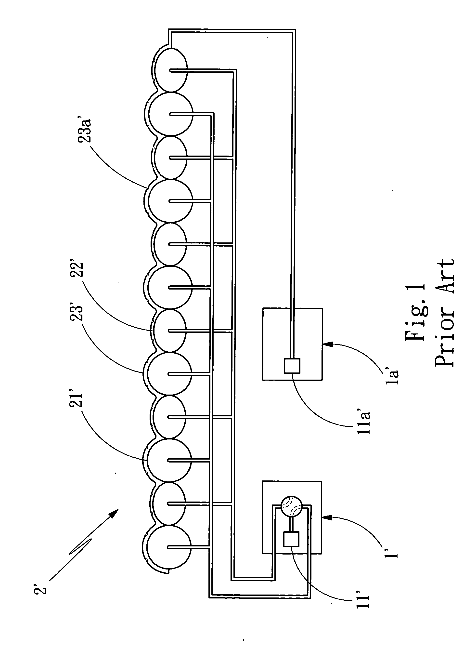
However, because of the two air pumps, the air pump (11′) and the air pump (1a′), in one heat sink structure for air mattress about prior arts, it increases cost and wastes power sources.

Method used


Image

  • Heat sink structure for air mattress
  • Heat sink structure for air mattress
  • Heat sink structure for air mattress

Examples


Embodiment Construction

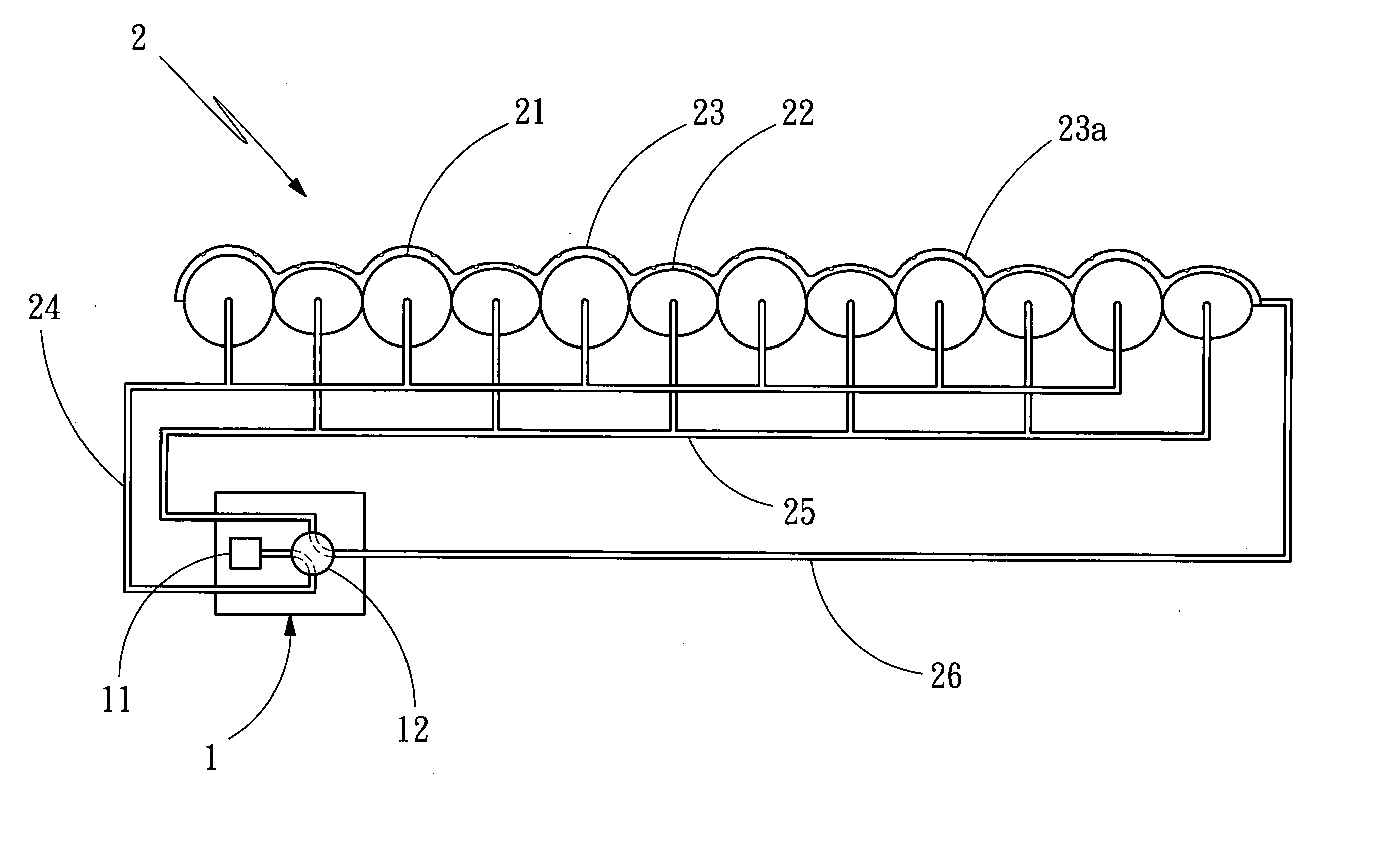
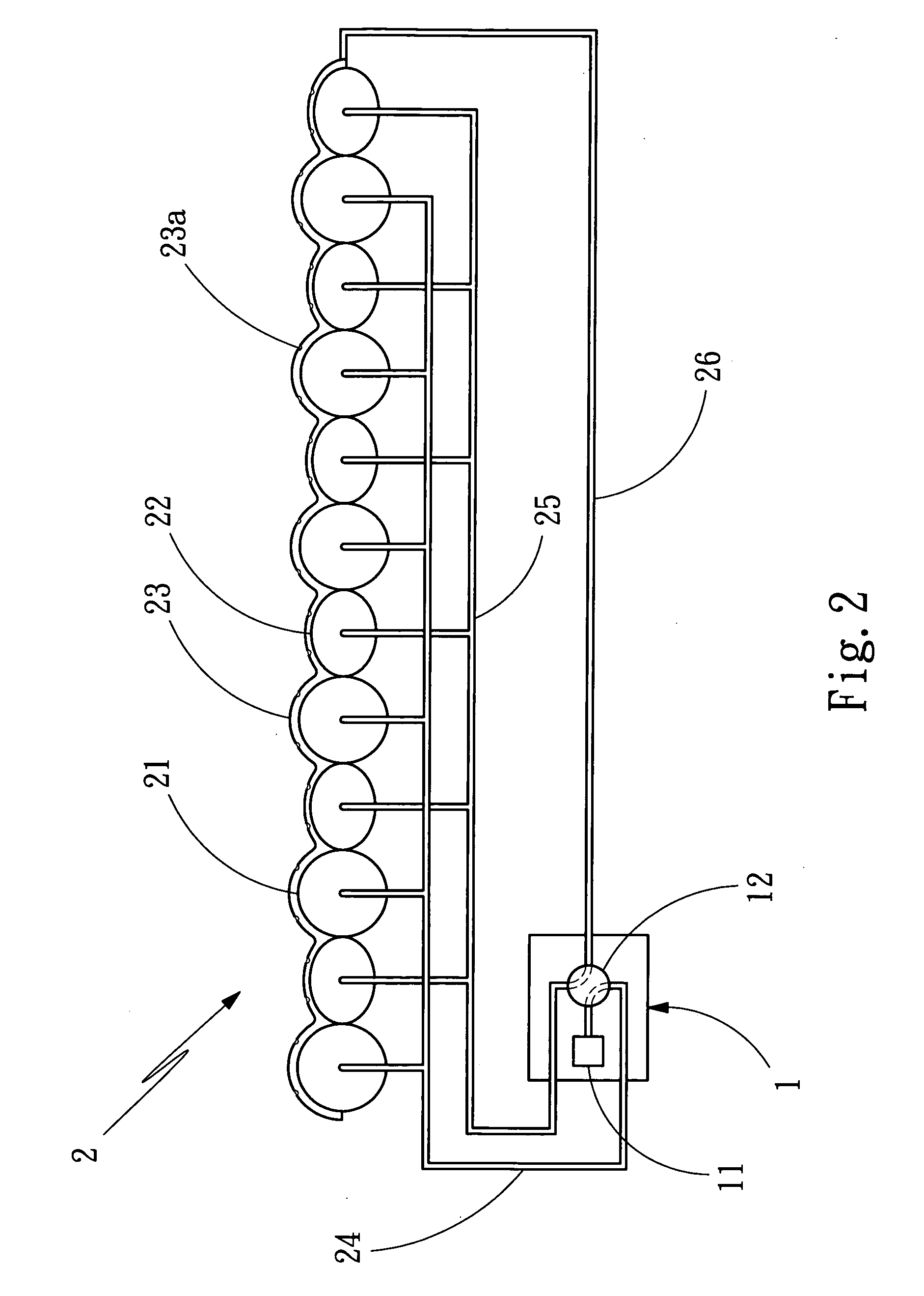
[0015] With reference to FIG. 2, the heat sink structure for air mattress in accordance with the present invention is mainly composed of a control unit (1) and an air mattress (2). The said control unit (1) has an air pump (11) and a controlling valve (12). The air pump (11) is a powered device for supply of compressed air, and the controlling valve (12) is a fluid connector for selecting some of components to connect. The air mattress (2) has a plurality of first airbags (21), a plurality of second airbags (22), and a heat sink layer (23), and there are numbers of the first airbags (21) and second airbags (22) arranged designedly while each airbag is a cannular structure which is expanded with pumping up and shrunken with draining off; and the heat sink layer (23) is a hollow structure made of breathed material, and some kinds of this material is porous material. As described above, the first airbags (21), the second airbags (22), and the heat sink layer (23) are connected to the c...


PUM


Abstract

A heat sink structure for air mattress mainly has a control unit having an air pump which is a powered device for supply of compressed air, and a controlling valve which is a fluid connector for selecting some of components to connect; and an air mattress having many groups of airbags arranged designedly while each airbag is a cannular structure which is expanded with pumping up and shrunken with draining off, and a heat sink layer which is a hollow structure; wherein the heat sink layer which is breathed and is connected to the controlling valve through an exhaust conduit; and each of the airbag groups is connected to the controlling valve through one conduit respectively and the controlling valve operated by the control unit selects any one group of the airbags to be connected for fluid flow and alternates the first conduit and the second conduit to connect with the air pump.

Description

BACKGROUND OF THE INVENTION [0001] 1. Field of the Invention [0002] The present invention relates to a heat sink structure for air mattress, and more particularly to an air mattress that is able to reclaim the air exhausted from airbags for dropping in temperature. [0003] 2. Description of Related Art [0004] A heat sink structure for air mattress about prior arts is airbags formed with a lot of apertures which drain out the inside air, and then the air takes some heat and damp away to make the air mattress more dry and comfortable. Usually, these apertures of the airbags are produced with laser processing, and these apertures cannot be too big otherwise the airbags cannot be pumped up. On the other hand, if the apertures are too small, it is insufficient to cool down and to exsiccate while the airbags cannot exhaust the inside air well. [0005] As FIG. 1 shows, a heat sink structure for air mattress about prior arts has a control unit (1′), a control unit (1a′) and an air mattress (2...

Claims


Application Information

Patent Timeline
IPC IPC(8): A47C27/08A47C21/04A47C27/10A61G7/057F25D17/06
CPCA47C21/044A47C27/082A61G7/05776A47C27/10A47C27/083A47C21/04
Inventor CHEN HAN, CHUN-CHU
Owner APEX MEDICAL CORPORATION
Learn More