Eureka AIR delivers breakthrough ideas for toughest innovation challenges, trusted by R&D personnel around the world.

Heat dissipation system and anti-backflow device

a heat dissipation system and anti-backflow technology, applied in the direction of electrical apparatus, electrical apparatus contruction details, electrical apparatus, etc., can solve the problems of inability to easily assemble the heat dissipation system b>1/b>, the effect of preventing deformation, good mechanical strength and simplified assembly procedur

Inactive Publication Date: 2007-01-04
DELTA ELECTRONICS INC
View PDF12 Cites 11 Cited by
  • Summary
  • Abstract
  • Description
  • Claims
  • Application Information

AI Technical Summary

Benefits of technology

[0011] As mentioned above, the heat dissipation system and the anti-backflow device thereof have the flappers, which are directly pivoted on the opening of the case. This structure can provide good mechanical strength for preventing the deformation. Accordingly, the assembling procedure can be simplified so as to reduce the production cost.

Problems solved by technology

However, if the heat generated during the operation of the electronic products is not properly removed in time, the efficiency of the electronic products would decrease and they may even be burnt out.
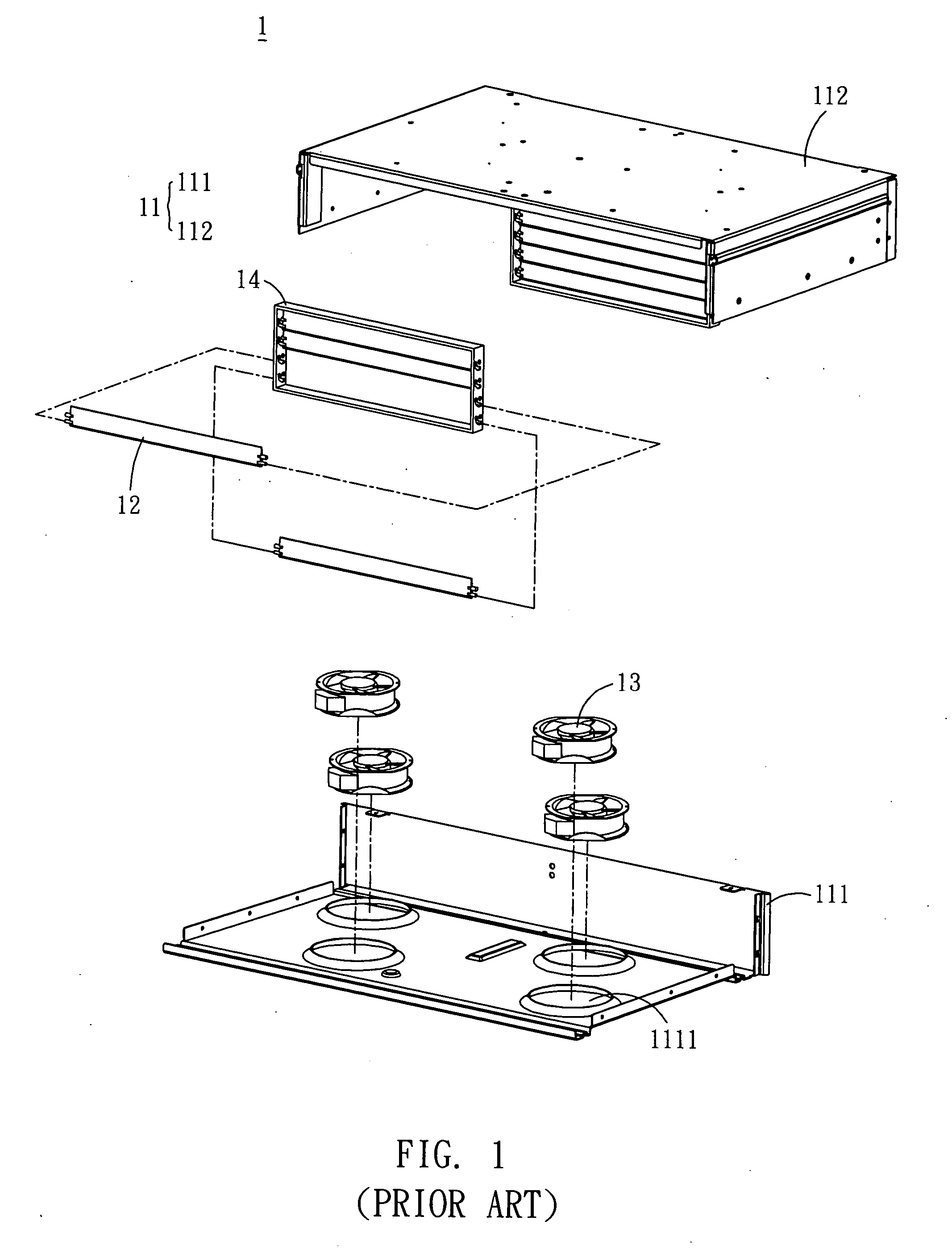
However, in the above mentioned assembling procedure, the fastening frames 14 may be deformed if the mechanical strength thereof is unreliable.
Thus, the heat dissipation system 1 can not be assembled easily, and the assembling steps become more complex.
This is inefficient for the present industry requirements.

Method used


Image

  • Heat dissipation system and anti-backflow device
  • Heat dissipation system and anti-backflow device
  • Heat dissipation system and anti-backflow device

Examples


Embodiment Construction

[0018] The present invention will be apparent from the following detailed description, which proceeds with reference to the accompanying drawings, wherein the same references relate to the same elements.

[0019] Please refer to FIG. 3 and FIG. 4, which show the exploded and schematic views of an anti-backflow device 3 according to a preferred embodiment of the invention. The anti-backflow device 3 includes a case 31, a plurality of flappers 32 and a partition 33.

[0020] In the embodiment, the case 31 includes a first housing 311 and a second housing 312. The first housing 311 has a plurality of inlets 3111. In this case, the first housing 311 and the second housing 312 are assembled by way of welding, riveting, screwing, adhering, wedging, clipping engaging, or the likes. Alternatively, the case 31 can be integrally formed. Accordingly, the case 31 can provide an opening 313 and a containing space constructed by the assemblage of the housings 311 and 312. The partition 33 is disposed...


PUM


Abstract

An anti-backflow device includes a case and a plurality of flappers. The case has at least one opening and a plurality of combining portion. The combining portions are disposed in two opposite sides of the opening. The combining portions and the case are integrally formed. The flappers are disposed in the opening in sequence. Each flapper has a first connecting portion and a second connecting portion, each of which pivots on one of the combining portions.

Description

BACKGROUND OF THE INVENTION [0001] 1. Field of Invention [0002] The invention relates to a heat dissipation system and an anti-backflow device thereof. [0003] 2. Related Art [0004] With the progress in technology, the performance of electronic products becomes much better. However, if the heat generated during the operation of the electronic products is not properly removed in time, the efficiency of the electronic products would decrease and they may even be burnt out. To remove the generated heat, the heat dissipation system has become one of the essential components in the present electronic products. [0005] Please refer to FIG. 1 and FIG. 2, which show the exploded and schematic views of a conventional heat dissipation system 1. The heat dissipation system 1 includes a case 11, a plurality of flappers 12, a plurality of fans 13 and two fastening frames 14. In this case, the case 11 includes a lower housing 111, which has a plurality of inlets 1111, and an upper housing 112. The ...

Claims


Application Information

Patent Timeline
IPC IPC(8): H05K5/00
CPCH05K7/2019
Inventor TAO, PENG-CHUCHUANG, TE-TSAIHUANG, WEN-SHI
Owner DELTA ELECTRONICS INC
Why Eureka
Eureka Blog
Learn More