Working Tool

a working tool and handguide technology, applied in the field of handguided working tools, can solve the problems of minimal mounting space of hand-guided working tools, in particular cut-off machines, and achieve the effect of improving sealing action

Active Publication Date: 2007-01-04
ANDREAS STIHL AG & CO KG
View PDF11 Cites 39 Cited by
  • Summary
  • Abstract
  • Description
  • Claims
  • Application Information

AI Technical Summary

Benefits of technology

[0006] The mounting channel enables the arrangement of the vacuum hose in an area that is required for mounting. The mounting channel enables excellent accessibility and unhindered mounting of the fastening element. In this way, a mounting space that otherwise is to be kept free only for mounting purposes can be utilized well and the working tool is provided with a compact configuration.
[0008] It is provided that the vacuum hose has an intake opening and an outlet opening for the vacuum channel and two mounting openings for the mounting channel. In this way, intake opening and outlet opening as well as the mounting openings can be arranged independent of one another on the vacuum hose. In this way, a favorable course of the vacuum channel can be achieved and the available mounting space can be utilized very well. In this connection, intake opening and outlet opening are arranged in particular on longitudinal sides of the vacuum hose. It is provided that a section of the mounting channel forms a section of the vacuum channel.
[0009] Advantageously, the vacuum hose is secured on a housing section of the working tool and on the combustion engine. The vacuum hose must extend in this area and the accessibility for screwing the cylinder onto the crankcase must be ensured in this area. In order to be able to compensate relative movements between the combustion engine and the housing section that are caused by vibrations of the motor, it is provided that the vacuum hose has at least one expansion fold between the housing section and the internal combustion engine. It is provided that the first end of the vacuum hose is secured in an opening in the housing section and the first end is provided with the mounting opening. The vacuum hose can be secured and positioned very well in the opening. Expediently, the second end of the vacuum hose is secured in a bore of the internal combustion engine wherein the second mounting opening is formed at the second end. Advantageously, the longitudinal axis of the bore in the combustion engine is positioned at an angle to the longitudinal axis of the opening in the housing section which angle is greater than 0°. Because of the angular arrangement of the bore and of the opening, the position of the vacuum hose is defined. When the vacuum hose is arranged in the opening and the bore, the intake opening and the outlet opening are aligned accordingly relative to the adjoining sections of the vacuum channel. In this way, a simple and safe mounting of the vacuum hose is realized.
[0010] In order to avoid leaks in the vacuum channel as a result of the mounting openings, it is provided that the working tool has a grip pipe and on the clamping shell of the grip pipe a plug is secured that closes off the first mounting opening. Without grip pipe, the working tool can be operated only with difficulty so that it is easily apparent to the operator that the grip pipe is missing. When the grip pipe is mounted the mounting opening is securely closed by the plug. In this way, it is ensured that the mounting opening is closed in operation of the working tool and the vacuum channel is seal-tight. No additional parts for closing the first mounting opening are required. Minimal mounting space for the vacuum channel is required when a section of the vacuum channel is formed in the housing section.
[0013] It is expedient to insert a sleeve into the vacuum hose. The sleeve is arranged in particular in an area of the vacuum hose in which the vacuum hose is secured in a housing section of the working tool. In this connection, the sleeve is designed such that is presses the outer circumference of the vacuum hose against the housing section so that in this way an improved sealing action between the vacuum hose and the housing section is effected.

Problems solved by technology

The mounting space available in hand-guided working tools, in particular, cut-off machines, is minimal.

Method used


Image

  • Working Tool
  • Working Tool
  • Working Tool

Examples


Embodiment Construction

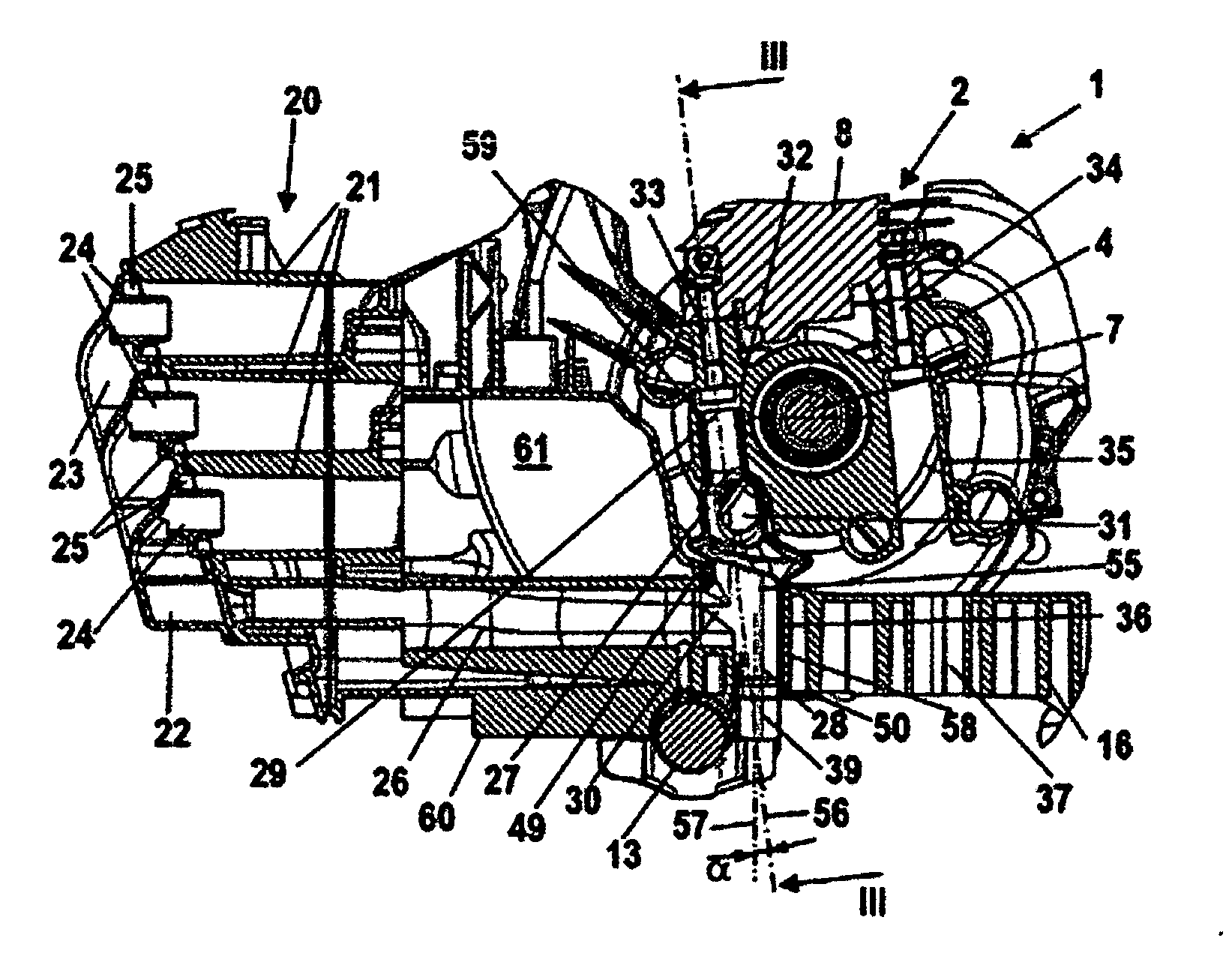
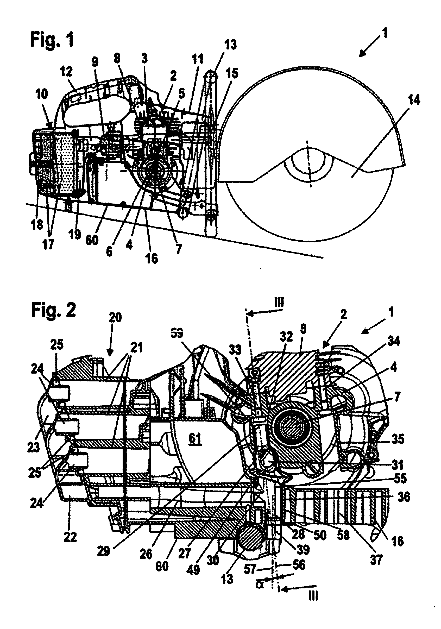
[0026] The working tool 1 illustrated schematically in longitudinal section in FIG. 1 is a cut-off machine having a housing 11 on which a handle 12 is arranged. The handle 12 is secured on the housing 11 of the working tool 1. The cut-off machine has a grip pipe 13 that extends transversely to the handle 12 and spans the housing 11. The working tool 1 has a tank housing 16 extending across the bottom 60 of the working tool 1. The working tool 1 has a tool, in this embodiment a cut-off wheel 14, that is driven by an internal combustion engine 2, in this case a two-stroke engine, arranged in the housing 11. The internal combustion engine 2 has a cylinder 8 in which a combustion chamber 3 is provided. The combustion chamber 3 is delimited by a piston 5 that drives by means of a connecting rod 6 a crankshaft 7 supported rotatably in the crankcase 4. A fan wheel, not illustrated in FIG. 1, for conveying cooling air to the internal combustion engine 2 is arranged on the crankshaft 7. The ...


PUM

PropertyMeasurementUnit
Angleaaaaaaaaaa
Areaaaaaaaaaaa

Abstract

A hand-guided working tool has an internal combustion engine having a crankshaft and a fan wheel driven by the crankshaft. An air cleaning device is provided for cleaning the combustion air for the internal combustion engine. The air cleaning device has a dirt chamber and a vacuum channel extending away from the dirt chamber and opening in the area of the fan wheel. A section of the vacuum channel is formed by a vacuum hose. The vacuum hose is arranged in a mounting area of a fastening element and comprises a mounting channel through which the fastening element is accessible.

Description

BACKGROUND OF THE INVENTION [0001] The invention relates to a hand-guided working tool, in particular, a cut-off machine or the like, that comprises an internal combustion engine that has a crankshaft that drives a fan wheel. The working tool further comprises a device for cleaning the combustion air for the internal combustion engine. The device comprises a dirt chamber. A vacuum channel extends away from the dirt chamber and opens in the area of the fan wheel. A section of the vacuum channel is formed in a vacuum hose. [0002] U.S. 2004 / 0094114 A1 discloses a cut-off machine provided with several cyclone pipes for cleaning the combustion air. The cyclone pipes separate particles from the combustion air which particles are sucked away by a vacuum hose that opens at a fan wheel. [0003] The mounting space available in hand-guided working tools, in particular, cut-off machines, is minimal. The vacuum hose opens between fan wheel and crankcase. This area must be accessible also for scre...

Claims


Application Information

Patent Timeline
IPC IPC(8): B25F3/00F01P1/02F02M35/02
CPCB01D50/002F02M35/022F02M35/06F02M35/08B01D50/20B01D46/00B01D46/12F02B63/02
Inventor UHL, KLAUS-MARTINFRIEDRICH, SEBASTIANRIEHMANN, JENS
Owner ANDREAS STIHL AG & CO KG
Why Eureka
Try Eureka