Indicator lamp
a technology of indicator lamp and light source, which is applied in the field of indicator lamp, can solve the problems of deteriorating long distance visual recognition property, lack of directivity of pin-point light emission, scattered light emission,
- Summary
- Abstract
- Description
- Claims
- Application Information
AI Technical Summary
Benefits of technology
Problems solved by technology
Method used
Image
Examples
first embodiment
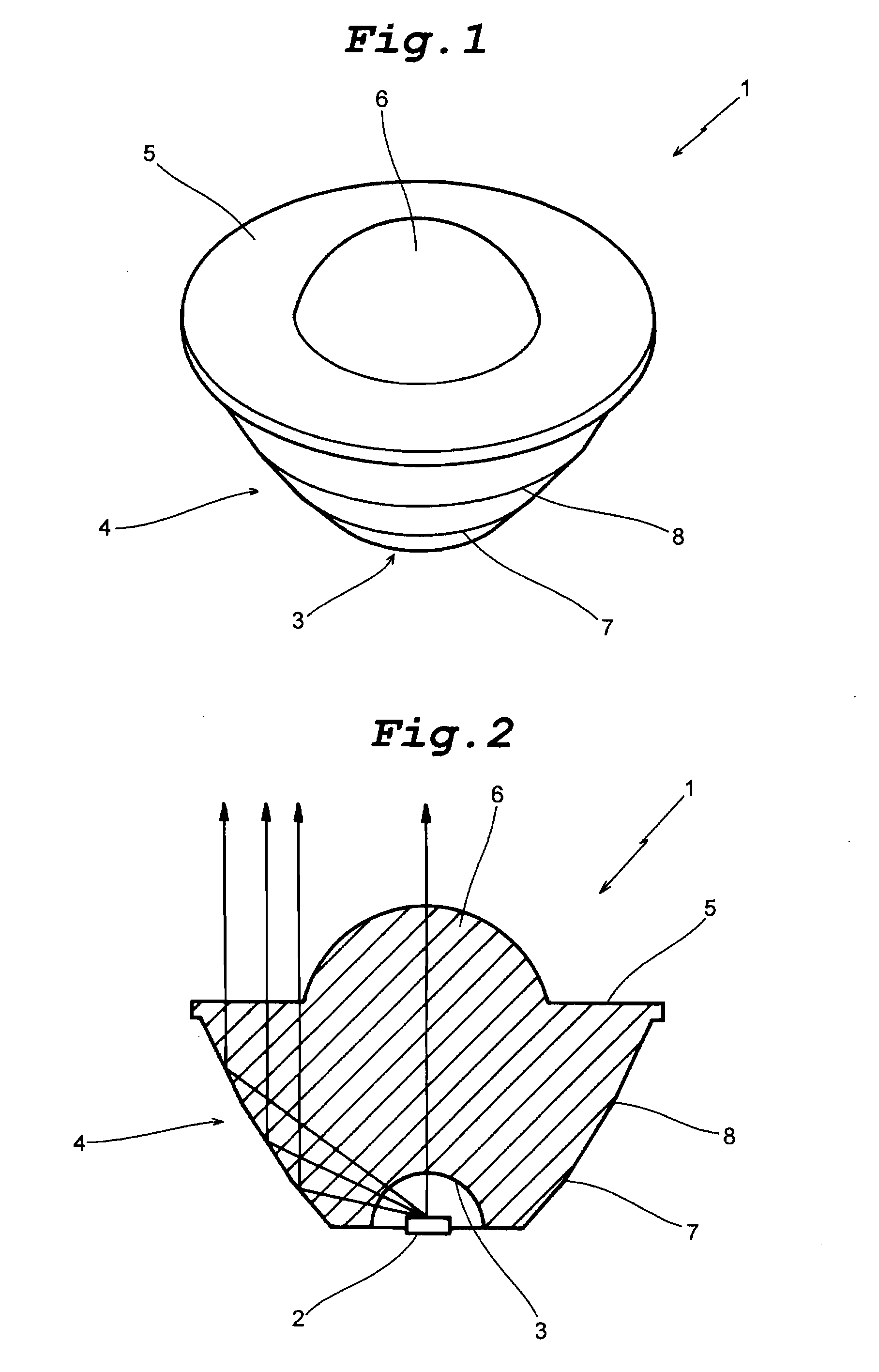
[0028]FIGS. 1 and 2 show the indicator lamp according to the invention. A light-emitting element lens 1 which is obtained by processing a transparent polymer material into a substantially conical shape, has a light-emitting element mounting cavity 3 formed in its bottom for disposing a light-emitting element 2 such as a LED in the cavity. The lens 1 has a sloped peripheral surface 4. The angle of the peripheral surface 4 with respect to the lens axis is made progressively smaller in three stages from the bottom toward the front of the lens. The lens front surface 5 is made flat and has a central forwardly convex lens part 6 (R5.78). The lens front surface 5 is made broader by forming a slightly projecting flange-like edge. As for the three-stage sloped parts of the peripheral surface 4, their angles with respect to the lens axis are set up to 40.61 degrees, 32.19 degrees and 26.87 degrees, respectively, (or may be other angles, of course) from the bottom toward the lens front. The c...
fourth embodiment
[0032]FIGS. 7 and 8 show the indicator lamp according to the invention. In this embodiment, the light-emitting element lens 31, which is made of a transparent polymer material such as acrylic resin and has a maximum outer diameter of about 21 mm and a height of about 12.5 mm, has an inverted conical shape with the outer diameter thereof increasing as one goes upwards. The light-emitting element 2 is disposed at the bottom of the lens, and its emitted light is converged and proceeds as a certain degree of emission light flux forwardly of the lens. This light-emitting element lens 31 has a peculiarly curved peripheral surface slightly outwardly swelling from the bottom towards the front surface 34 of the lens (a plurality of slipped surface parts being possible instead of the curved peripheral surface). The lens front surface 34 has an outer flat surface part 35 and a central forwardly convex lens part 36 (R5) forwardly projecting from a position slightly on the rear side of the lens ...
fifth embodiment
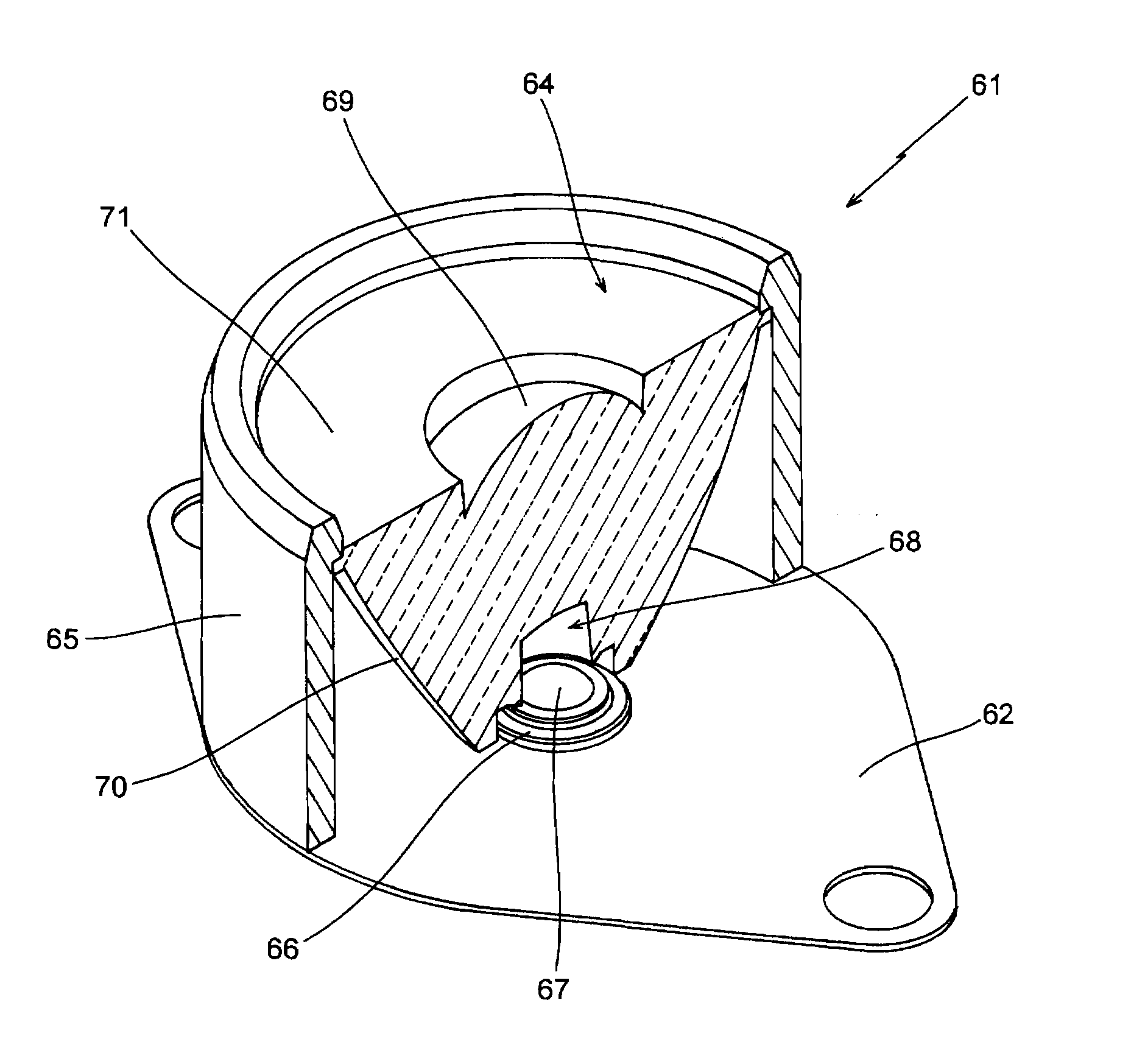
[0039] While the above embodiment has concerned with the structure that the central convex lens part 70 is provided on the front surface of the full reflection lens 64, this is by no means limitative; for instance, the lens front surface may be made fully flat and free from any central convex lens part. Even in this case, although not a perfect parallel light flux as in the case of the indicator lamp 61 described above, this embodiment of the indicator lamp can provide a converging function to provide a roughly parallel light flux of a simple shape. Although not illustrated, with such an arrangement that light is not caused by the front surface 68a of the cavity 68 to proceed straight but diffracted for deviation toward the lens axis, it is possible to provide a more suitable converging function to provide light close to a parallel light flux.
POSSIBILITY OF INDUSTRIAL UTILIZATION
[0040] In the indicator lamp according to the invention, the light-emitting element lens is constituted ...
PUM
 Abstract
Description
Claims
Application Information
 - R&D
- Intellectual Property
- Life Sciences
- Materials
- Tech Scout
- Unparalleled Data Quality
- Higher Quality Content
- 60% Fewer Hallucinations
Browse by: Latest US Patents, China's latest patents, Technical Efficacy Thesaurus, Application Domain, Technology Topic, Popular Technical Reports.
© 2025 PatSnap. All rights reserved.Legal|Privacy policy|Modern Slavery Act Transparency Statement|Sitemap|About US| Contact US: help@patsnap.com


