
Optical member, light source apparatus, display apparatus, and terminal apparatus

a technology of light source apparatus and terminal apparatus, which is applied in the direction of lighting and heating apparatus, instruments, lenses, etc., can solve the problems of insufficient improvement of brightness at low directivity of light that passes through the edge portions of the screen, and unlikely to reach a viewer. , to achieve the effect of improving light directivity and keeping the light utilization ratio high

Active Publication Date: 2006-12-28
NEC LCD TECH CORP
View PDF11 Cites 144 Cited by
  • Summary
  • Abstract
  • Description
  • Claims
  • Application Information

AI Technical Summary

Benefits of technology

[0026] An object of the present invention is to provide an optical member that has a high light utilization ratio, that increases the directivity of planarly-emitted light, and that can make the brightness uniform with respect to the point of observation; to provide a light source apparatus that efficiently emits planar light with high directivity in a uniform fashion with respect to the point of observation; to provide a display apparatus that has a high light utilization ratio and uniform brightness in the screen; and to provide a terminal apparatus.
[0027] The optical member according to the first aspect of the present invention has a deflecting element for deflecting and emitting incident light, and an element for restricting the direction of light s rays that is intermediately disposed in the optical path of the light restricts the traveling direction of the light to the direction parallel to the optical path, and increases the directivity of the light.
[0028] In the present invention, planar light can be directed to the point of observation by using a deflecting element to defect light. The directivity of light can be improved while the transmissivity at which light passes through the element for restricting the direction of light rays can be increased and made uniform by disposing the element in the optical path of light and restricting the traveling direction of the light to the direction that is parallel to the optical path. The brightness can thereby be made uniform while the light utilization ratio is kept high.

Problems solved by technology

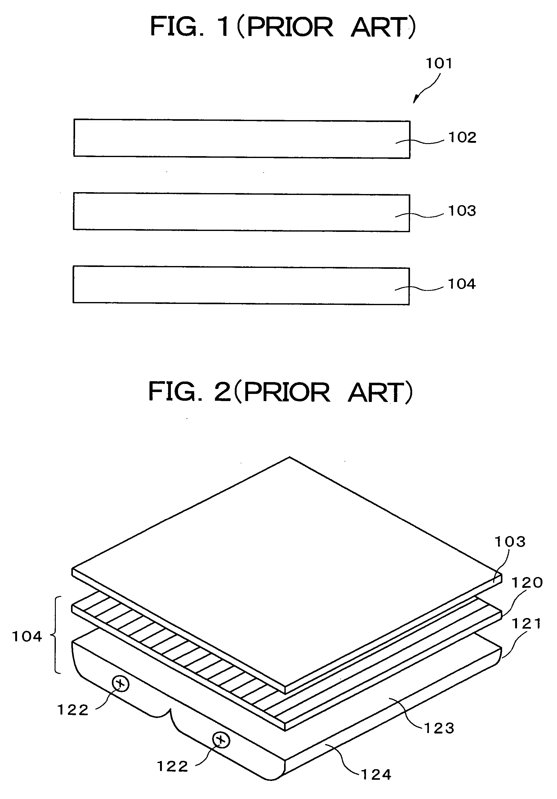
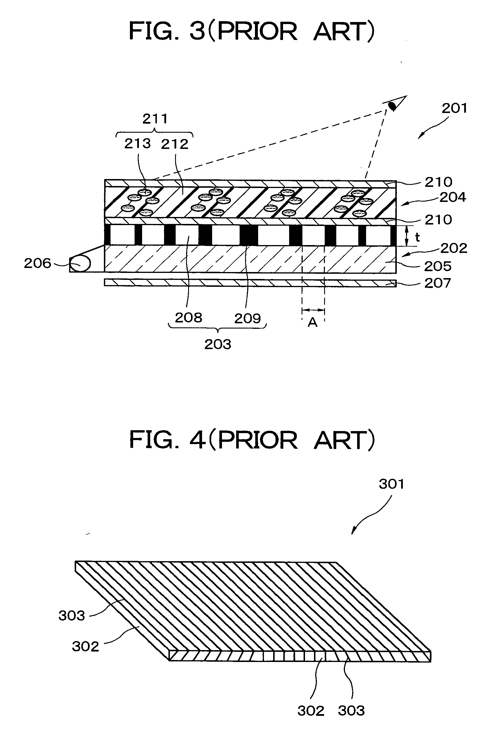
However, the display apparatus cited in Japanese Laid-Open Patent Application No. 9-244018 (FIG. 3) has the following problems.
For this reason, when the narrow-viewing-angle display is used, light emitted from the edge portions of the screen is unlikely to reach a viewer who is positioned in the front position.
There is a problem in this case, however, in that the directivity of the light that passes through the edge portions of the screen is lower than the directivity of the light that passes through the center area of the screen.
However, the above-described art has the following problems.
In such a case, however, the brightness at the edge portions of the screen cannot be sufficiently improved.
The light in the direction perpendicular to the surface of the planar light-emitting source is inefficient because more light is absorbed by the significantly sloped light-blocking layer 411.
As a result, the light utilization ratio is dramatically reduced, and power consumption is increased or image quality reduced.

Method used


Image

  • Optical member, light source apparatus, display apparatus, and terminal apparatus
  • Optical member, light source apparatus, display apparatus, and terminal apparatus
  • Optical member, light source apparatus, display apparatus, and terminal apparatus

Examples


first embodiment

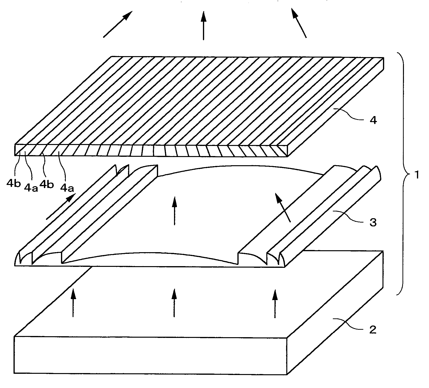
[0080] Embodiments of the present invention are described in detail below with reference to the attached diagrams. First, the present invention is described. FIG. 6 is perspective view showing the light source apparatus of the present embodiment. FIG. 7A is a perspective view and a plan view schematically showing the operation of the light source apparatus. FIG. 7B is a graph showing the deflection characteristics of a Fresnel lens sheet, wherein the position in the luminous flux emitted from the Fresnel lens sheet is plotted on the horizontal axis, and the angle at which brightness is at its maximum is plotted on the vertical axis. FIG. 7C is a graph showing the characteristics according to which the direction of light rays is restricted by a louver as an element for restricting the direction of light rays, wherein the position in the luminous flux emitted from the louver is plotted on the horizontal axis, and the angle at which brightness is at its maximum is plotted on the vertic...

second embodiment

[0089] the present invention is described next. FIG. 8 is a cross-sectional view showing the display apparatus of the present embodiment. FIG. 9 is a perspective view showing the Fresnel lens in the display apparatus. FIG. 10 is a side view showing the positional relationship between the Fresnel lens and the louver in the display apparatus. FIG. 11 is a perspective view showing the terminal apparatus of the present embodiment.

[0090] The display apparatus 7 of the present embodiment has a light source apparatus 1, transparent / scattering switching element 5, and transmissive liquid crystal display panel 6 in the stated order, as shown in FIG. 8. The light emitted from the light source apparatus 1 enters the liquid crystal display panel 6 via the transparent / scattering switching element 5. The liquid crystal display panel 6 is, for example, a panel with a 15-inch diagonal, and the size of the display area is 228 mm in the vertical direction and 304 mm in the horizontal direction.

[0091...

third embodiment

[0135] the present invention is described next. FIG. 20 is a cross-sectional view showing the display apparatus of this embodiment. FIG. 21 is a side view showing the positional relationship between the Fresnel lens sheet and the louver in the display apparatus. FIG. 22A is a perspective view that schematically shows the operation of the apparatus; FIG. 22B is a graph showing the characteristics according to which the direction of light rays is restricted by a louver, wherein the X-axis coordinate in the luminous flux emitted from the louver is plotted on the horizontal axis, and the angle at which brightness is at its maximum is plotted on the vertical axis; and FIG. 22C is a graph showing the deflection characteristics of a Fresnel lens, wherein the X-axis coordinate in the luminous flux emitted from the Fresnel lens sheet is plotted on the horizontal axis, and the angle at which brightness is at its maximum is plotted on the vertical axis.

[0136] The light source apparatus of the ...


PUM


Abstract

A planar light source, Fresnel lens sheet, and louver are disposed in the stated order in a light source apparatus. The Fresnel lens sheet deflects and focuses in one dimension light that has entered from the planar light source. The louver is disposed in the optical path of the light emitted from the Fresnel lens sheet, and the directivity of the light can be increased by restricting the traveling direction of the light to the focal direction of the Fresnel lens sheet. The light utilization ratio can thereby be increased, the directivity of planarly emitted light can be increased, and the brightness can be made uniform at the point of observation.

Description

BACKGROUND OF THE INVENTION [0001] 1. Field of the Invention [0002] The present invention relates to an optical member that increases the directivity of light emitted in the form of a plane, a light source apparatus that can emit light with high directivity, a display apparatus provided with the light source apparatus, and a terminal apparatus in which the display apparatus is mounted. [0003] 2. Description of the Related Art [0004] A liquid crystal display apparatus (hereinafter abbreviated as “LCD”) is conventionally used as a flat display apparatus. An LCD is widely used as the display apparatus of a mobile terminal. In such a mobile terminal, there are many cases in which one does not want to have other people view displayed information, and the LCD preferably has a narrow viewing angle in such cases. However, there are also cases in which information displayed on a mobile terminal is shared and viewed by other people, and the LCD preferably has a wide viewing angle in such case...

Claims


Application Information

Patent Timeline
IPC IPC(8): F21V7/04
CPCG02B3/08G02B6/0053F21V33/0052F21V13/02G02F2001/133607G02F1/133607
Inventor NIIOKA, SHINYASUMIYOSHI, KENUEHARA, SHIN-ICHIIMAI, MASAOTAKATORI, KENICHIOKUMURA, FUJIO
Owner NEC LCD TECH CORP
Learn More