
Optical amplifier and optical fiber

an optical amplifier and optical fiber technology, applied in the field of optical amplifiers and optical fibers, can solve the problems of low gain of edfa, inability to obtain sufficient gain, and nonlinear effects (nonlinear optical effects) that have shown up, and achieve high reliability and effectively reduce four-wave mixing

Inactive Publication Date: 2006-12-28
FUJITSU LTD
View PDF9 Cites 8 Cited by
  • Summary
  • Abstract
  • Description
  • Claims
  • Application Information

AI Technical Summary

Benefits of technology

[0044] The present invention was made under the background circumstances described above. An object of the present invention is to provide a high-quality optical amplifier with high reliability for performing wide-band high-output optical amplification by effectively reducing four-wave mixing.
[0045] Another object of the present invention is to provide a high-quality optical fiber with high reliability used as an optical amplification medium for performing wide-band high-output optical amplification by effectively reducing four-wave mixing.

Problems solved by technology

As can be seen from FIG. 26, however, the gain of the EDFA becomes low.
Therefore, a sufficient gain cannot be obtained.)
With an increase in the number of channels and the intensity of output light per channel, however, in recent years marked nonlinear effects (nonlinear optical effects) have showed up.
If this phenomenon occurs, the linearity of an optical response is lost.
If the wavelength of the interference light matches one of wavelengths contained in multiplexed signal light, then crosstalk occurs and communication quality deteriorates.
Four-wave mixing which occurs on an optical fiber transmission line causes noise or waveform distortion, resulting in deterioration in signal quality.
Therefore, four-wave mixing tends to have a bad influence, compared to the case where C band amplification is performed.
It is recognized that even if an EDF having negative chromatic dispersion is used in WDM transmission, four-wave mixing cannot be suppressed effectively.

Method used


Image

  • Optical amplifier and optical fiber
  • Optical amplifier and optical fiber
  • Optical amplifier and optical fiber

Examples


Embodiment Construction

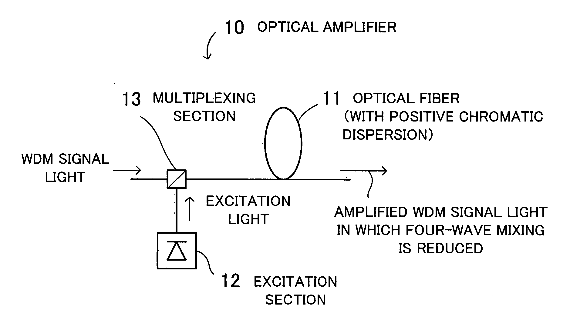
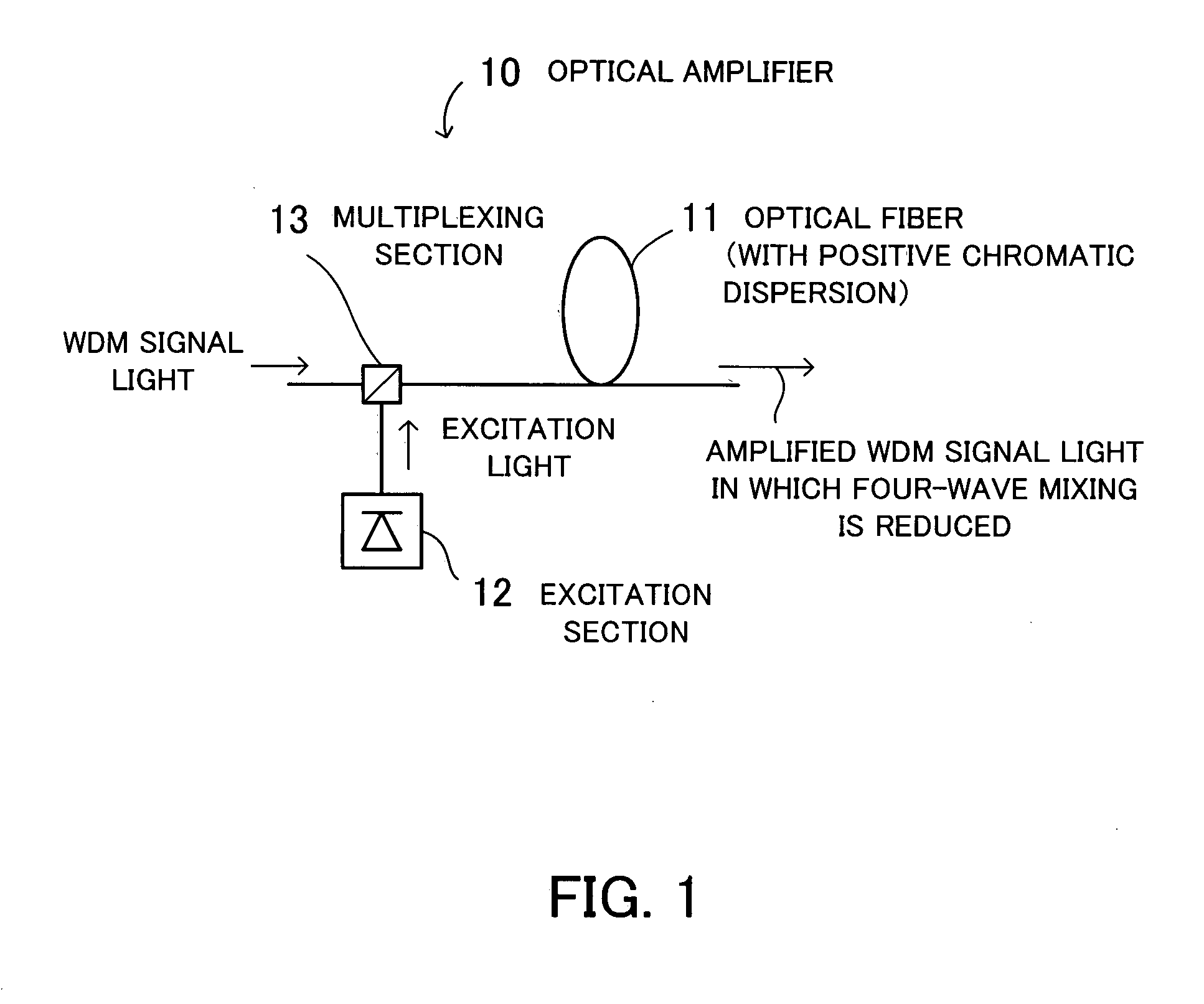
[0074] An embodiment of the present invention will now be described with reference to the drawings. FIG. 1 is a view for describing the principles underlying an optical amplifier according to the present invention. An optical amplifier 10 comprises an optical fiber 11, an excitation section 12, and a multiplexing section 13 and amplifies an optical signal.

[0075] The optical fiber 11 is an optical amplification medium which has positive chromatic dispersion in a signal band where signal light to be propagated is included and which amplifies a wavelength division multiplex (WDM) signal containing a plurality of wavelengths. The excitation section 12 inputs excitation light to the optical fiber 11.

[0076] The multiplexing section 13 combines the WDM signal light and the excitation light. A multiplexed signal is inputted to the optical fiber 11. The WDM signal light is amplified in the optical fiber 11 by the excitation light and is outputted from the optical fiber 11. The optical fibe...


PUM


Abstract

An optical amplifier that improves the quality of WDM transmission by reducing four-wave mixing. An optical fiber has positive chromatic dispersion in a signal band and is used as an optical amplification medium for amplifying a wavelength division multiplex signal. An excitation section inputs excitation light to the optical fiber. In order to actualize mismatching of phases of optical signals with different wavelengths to be propagated, the optical fiber has positive chromatic dispersion in a signal band by which there is a great difference between a signal frequency, being a frequency of a signal to be amplified, and a zero-dispersion frequency, being a frequency at which chromatic dispersion is zero. As a result, the optical fiber functions as an optical amplification medium in which four-wave mixing is suppressed.

Description

CROSS-REFERENCE TO RELATED APPLICATIONS [0001] This application is based upon and claims the benefits of priority from the prior Japanese Patent Application No. 2005-182425, filed on Jun. 22, 2005, the entire contents of which are incorporated herein by reference. BACKGROUND OF THE INVENTION [0002] 1. Field of the Invention [0003] This invention relates to an optical amplifier and an optical fiber, more particularly, to an optical amplifier for amplifying an optical signal and an optical fiber which functions as an optical amplification medium for amplifying an optical signal. [0004] 2. Description of the Related Art [0005] It is hoped that more advanced services will be provided via optical communication networks. Wavelength division multiplexing (WDM) begins to be widely introduced as an optical transmission technique. WDM multiplexes a plurality of optical signals with different wavelengths into a single optical fiber. [0006] With WDM, wavelength division multiplex signals contai...

Claims


Application Information

Patent Timeline
IPC IPC(8): H01S3/00G02B6/036G02B6/02H01S3/10
CPCH01S3/0064H01S3/06725H01S3/06729H01S3/06754H01S3/06758H04B2210/256H01S3/09415H01S2301/04H04B10/291H04B2210/003H01S3/094011
Inventor SHUKUNAMI, NORIFUMIINAGAKI, SHINYA
Owner FUJITSU LTD
Learn More