Control device for servo die cushion
a technology of control device and die cushion, which is applied in the direction of program control, shape safety device, forging/pressing/hammering apparatus, etc., can solve the problems of low frequency vibration in the machine, and it is difficult to increase the force gain for rapid acceleration or deceleration
- Summary
- Abstract
- Description
- Claims
- Application Information
AI Technical Summary
Benefits of technology
Problems solved by technology
Method used
Image
Examples
first embodiment
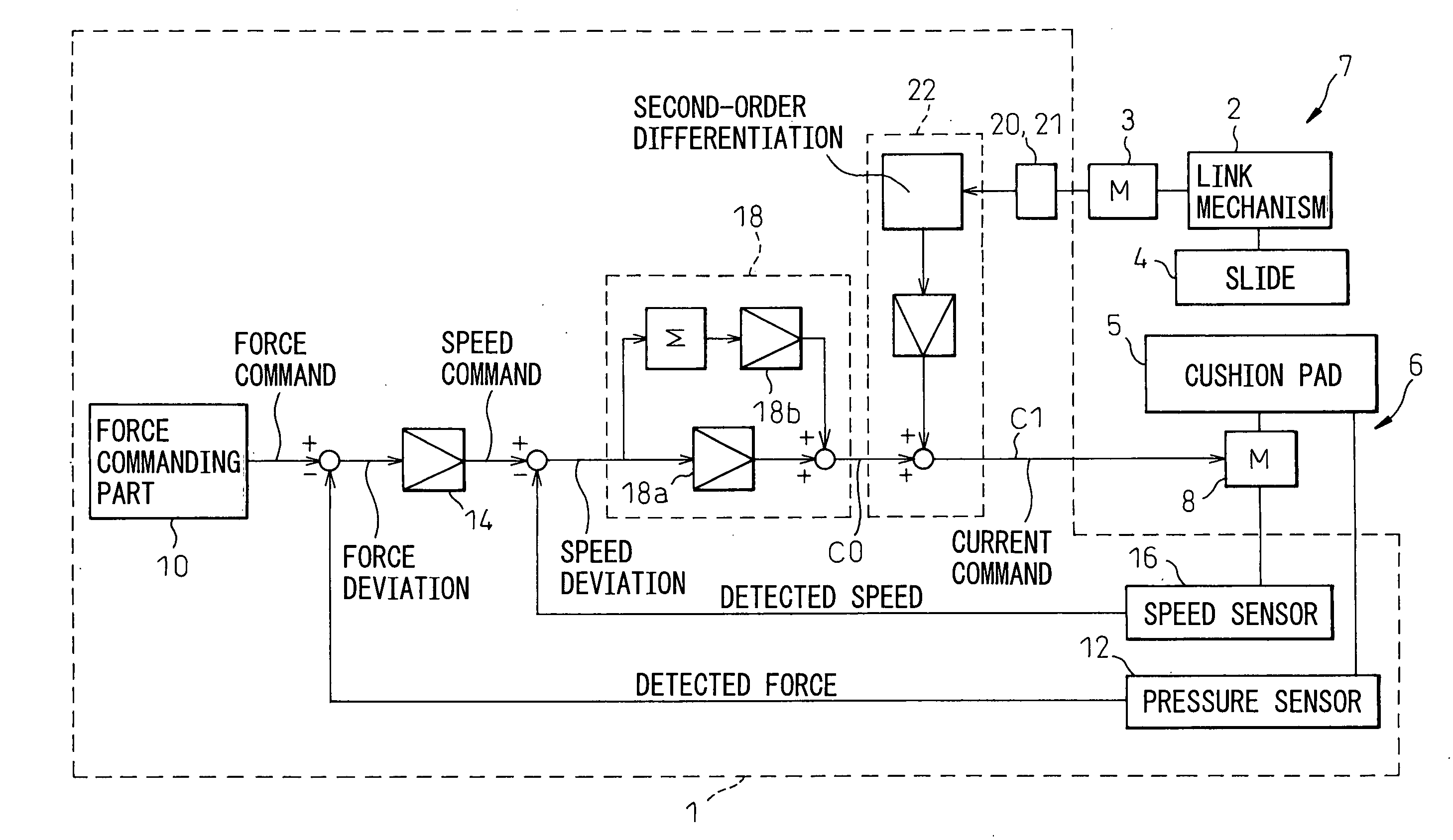
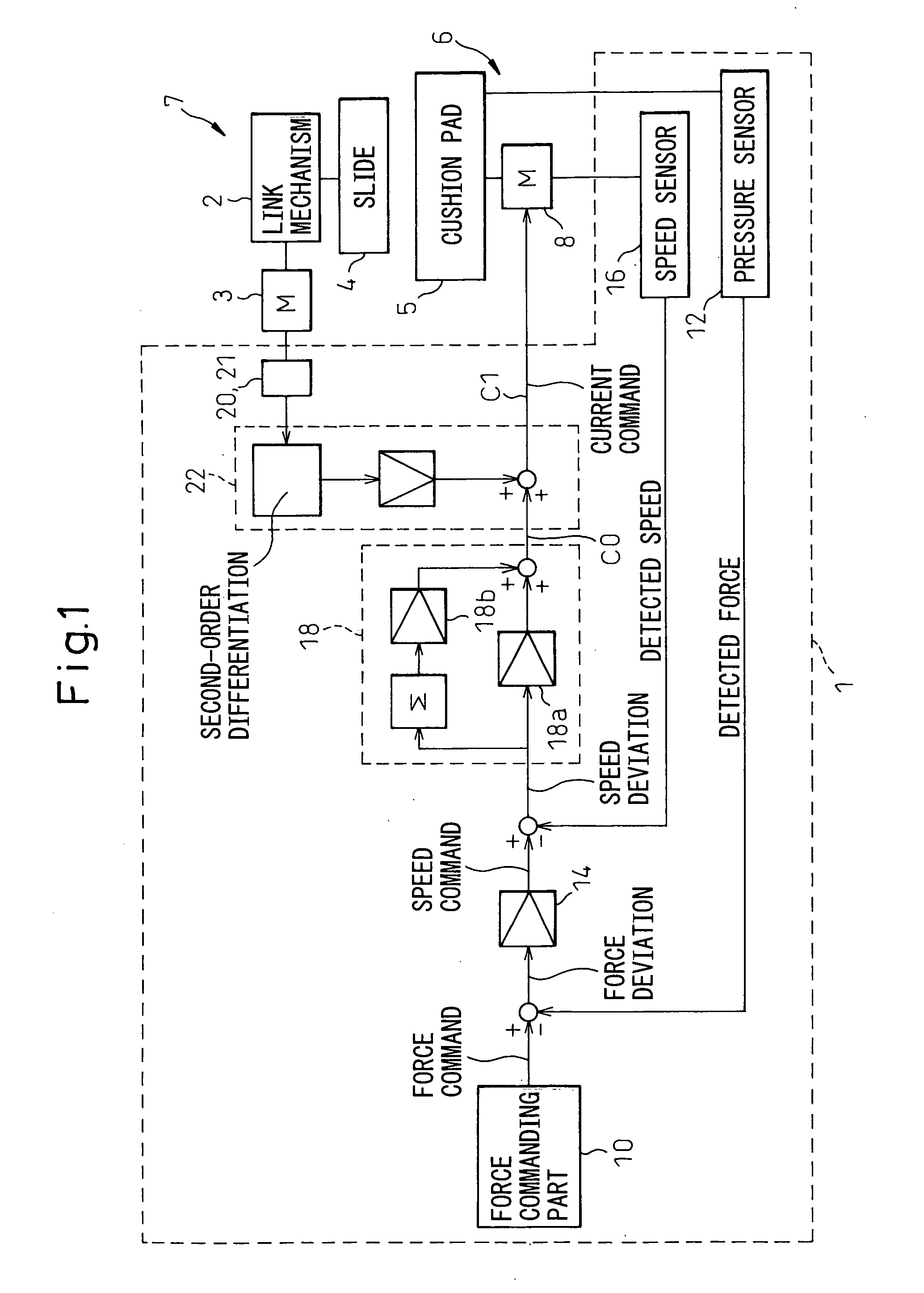
[0026] As shown in FIG. 1, a control device 1 according to the invention is used for a press machine 7 having a slide 4 driven by a servomotor 3 via a suitable link mechanism 2 and a die cushion mechanism 6 including a cushion pad 5 capable of moving corresponding to the motion of the slide 4. The control device controls a servomotor 8 for driving the cushion pad 5 so as to generate a predetermined force or pressure between the slide 4 and the cushion pad 5. As components other than the control device 1 may be the same as the conventional components, a detailed description of the components is omitted.
[0027] As shown in FIG. 1, the control device 1 of the first embodiment includes a force commanding part 10 for generating a force command including a commanded force value to be generated between the slide 4 and the die cushion mechanism 6, a force detecting part 12 such as a force sensor for detecting a force generated between the slide 4 and the die cushion mechanism 6, a speed comm...
second embodiment
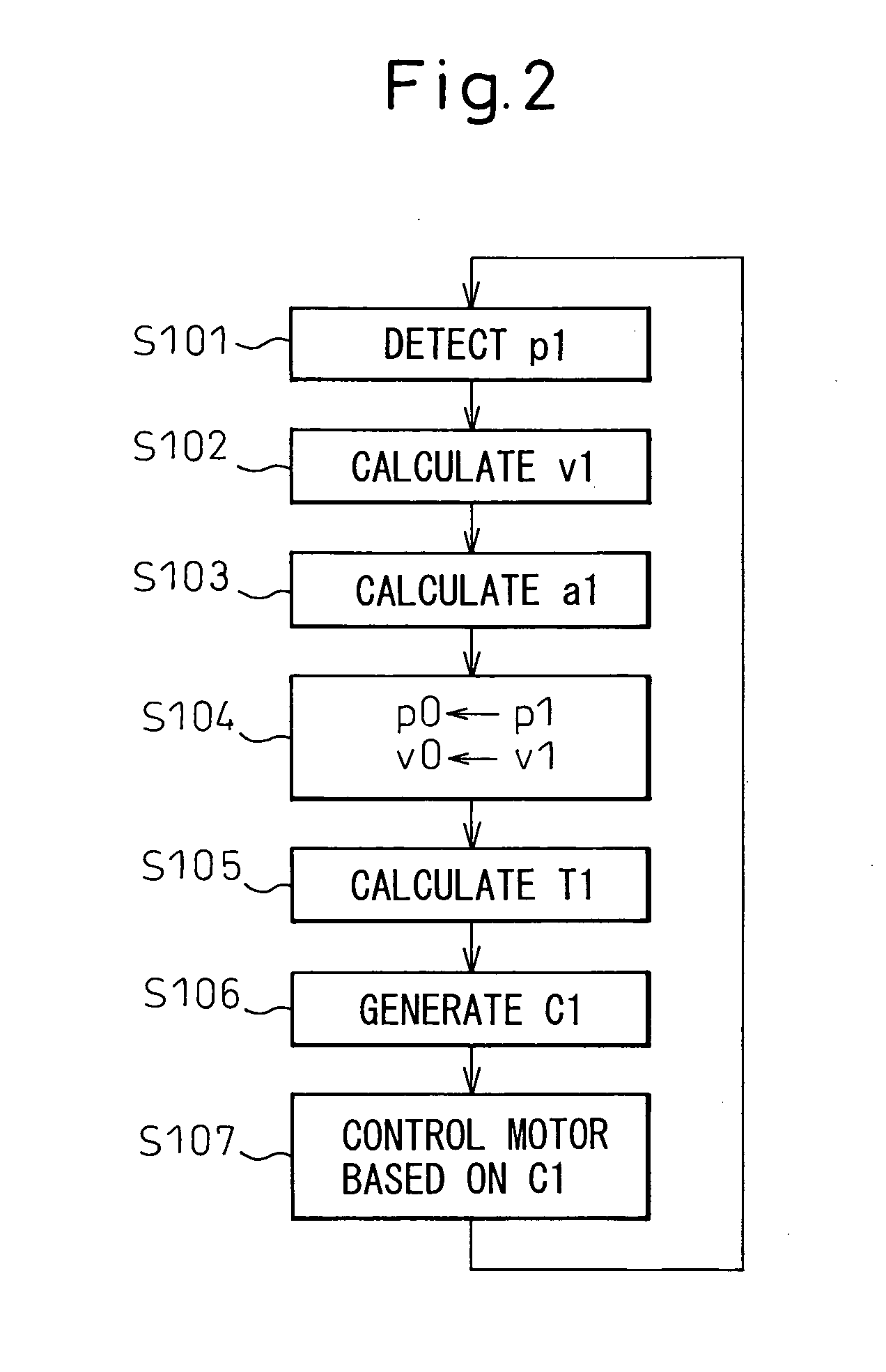
[0036] As described above, in the second embodiment, the correcting part 22′ corrects the force gain. In other words, steps S101′ to S104′ of FIG. 4 are the same as steps S101 to S104 of FIG. 2. However, in step S105′, a force gain Gp1 is calculated by using the above slide acceleration a1 and the following equation (4), instead of calculating the correction torque.
Gp1=k2·Gp0·a1 (4)
[0037] wherein k2 is a constant number and Gp0 is an initial force gain.
[0038] According to the prior art, in the speed commanding part 14, the speed command could be generated by multiplying a force gain Gp0 by a force deviation calculated by a differential between the commanded force value and the detected force value. However, in the present invention, a speed command V1 is generated and corrected by using a force gain Gp1 which can be varied corresponding to the acceleration of the slide (step S106′). Further, a current command C1′ is generated and corrected based on the speed command V1 (step S107...
third embodiment
[0041] As shown in FIG. 7, in the third embodiment, the correcting part 22″ corrects the speed gain. In other words, steps S101″ to S104″ of FIG. 7 are the same as steps S101 to S104 of FIG. 2. However, in step S105″, a speed gain Gv1 is calculated by using the above slide acceleration a1 and a following equation (5).
Gv1=k3−Gv0·a1 (5)
[0042] wherein k3 is a constant number and Gv0 is an initial speed gain.
[0043] According to the prior art, in the current commanding part 18, the current command could be generated by multiplying the speed gain Gv0 by a speed deviation calculated by a differential between the commanded speed value and the detected speed value. However, in the present invention, a current command C1″ is generated and corrected by using a speed gain Gv1 which can be varied corresponding to the acceleration of the slide (step S106″). Therefore, the servomotor 8 may also be optimally controlled by the current command C1″ (step S107″).
[0044] Also, in the third embodiment...
PUM
| Property | Measurement | Unit |
|---|---|---|
| Speed | aaaaa | aaaaa |
| Acceleration | aaaaa | aaaaa |
| Current | aaaaa | aaaaa |
Abstract
Description
Claims
Application Information
 - R&D
- Intellectual Property
- Life Sciences
- Materials
- Tech Scout
- Unparalleled Data Quality
- Higher Quality Content
- 60% Fewer Hallucinations
Browse by: Latest US Patents, China's latest patents, Technical Efficacy Thesaurus, Application Domain, Technology Topic, Popular Technical Reports.
© 2025 PatSnap. All rights reserved.Legal|Privacy policy|Modern Slavery Act Transparency Statement|Sitemap|About US| Contact US: help@patsnap.com


