Foreign matter removing apparatus
a foreign matter and apparatus technology, applied in the direction of chemistry apparatus and processes, cleaning equipments, printed circuit manufacture, etc., can solve the problems of foreign matter not being removed sufficiently, mounted parts become bumps, and the printed board unit itself is destroyed, so as to facilitate the intensity of shock received and effectively remove foreign matter
- Summary
- Abstract
- Description
- Claims
- Application Information
AI Technical Summary
Benefits of technology
Problems solved by technology
Method used
Image
Examples
second embodiment
[0069] Next, the invention will be explained.
[0070]FIG. 4 illustrates a schematic diagram (a) showing the second embodiment of the foreign matter removing apparatus of the invention, and an enlarged view (b) of collected foreign matter.
[0071] As shown in part (a) of FIG. 4, the foreign matter removing apparatus 2 of the second embodiment includes a blowout fan unit 21 provided above the printed board unit 10 for blowing gas toward the printed board unit 10, and a vacuum unit 22 provided below the printed board unit 10 for sucking gas from the printed board unit 10. Foreign matter dropped by vibration is forcibly removed from the printed board unit 10 by the blowout fan unit 21 and the vacuum unit 22.
[0072] According to the second embodiment, the vacuum unit 22 is provided with a filter 23 for collecting foreign matter included in gas sucked by the vacuum unit 22, and the filter 23 can collect the dropped foreign matter 24 (see part (b) of FIG. 4). If the foreign matter 24 collecte...
third embodiment
[0074] Next, the invention will be explained.
[0075]FIG. 5 illustrates a schematic diagram (a) showing a foreign matter removing apparatus of the third embodiment, and a partial enlarged view (b) thereof.
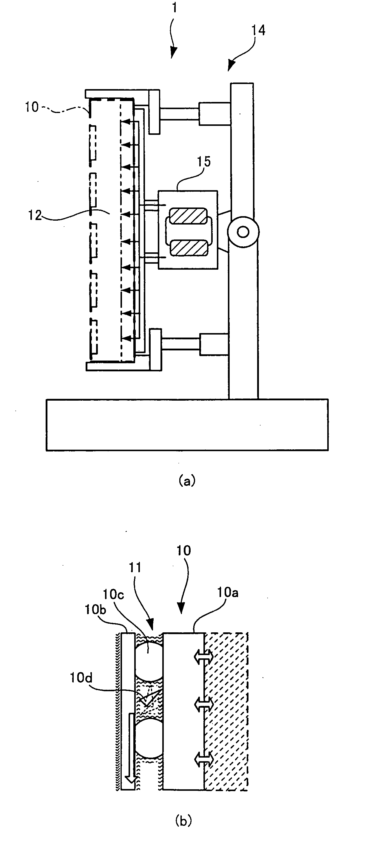
[0076] As shown in part (a) of FIG. 5, the holder 14 of the foreign matter removing apparatus 3 can hold the printed board unit 10 with any angle. As shown in part (b) of FIG. 5, continuous shock wave generated by the electromagnetic vibrator 15 is transmitted to the printed board unit 10 in a state in which the mounting surface 11 is held downwardly.
[0077] With this structure, as shown in part (c) of FIG. 5, the foreign matter 31 entered into a connector 30 mounted on the printed board unit 10 can effectively drop downward.
fourth embodiment
[0078] Next, the invention will be explained.
[0079]FIG. 6 shows an outline of a foreign matter removing apparatus of a fourth embodiment, and FIG. 7 is a graph showing a shock value monitoring result by the foreign matter removing apparatus shown in FIG. 6.
[0080] As shown in parts (a) and (b) of FIG. 6, the foreign matter removing apparatus 4 includes G sensors 40 which measure the intensity of shock received by various portions of the printed board unit 10 by continuous shock wave, a monitoring unit 41 which monitors shock values measured by the G sensors 40, cables 42 which transmit measuring signals from the G sensors 40 to the monitoring unit 41, and a display unit 43 which displays a monitoring result on a screen.
[0081] As shown in FIG. 7, acceleration G (intensity of shock) received by the various portions (CH1, CH2, CH3, . . . ) of the printed board unit 10 from the G sensors 40 and the monitoring unit 41 is displayed on the display unit 43. With this, it is possible to eas...
PUM
 Abstract
Description
Claims
Application Information
 - R&D
- Intellectual Property
- Life Sciences
- Materials
- Tech Scout
- Unparalleled Data Quality
- Higher Quality Content
- 60% Fewer Hallucinations
Browse by: Latest US Patents, China's latest patents, Technical Efficacy Thesaurus, Application Domain, Technology Topic, Popular Technical Reports.
© 2025 PatSnap. All rights reserved.Legal|Privacy policy|Modern Slavery Act Transparency Statement|Sitemap|About US| Contact US: help@patsnap.com


