
Patient repositioning device and method

Inactive Publication Date: 2006-12-28
ONCOLOG MEDICAL QA
View PDF15 Cites 19 Cited by
  • Summary
  • Abstract
  • Description
  • Claims
  • Application Information

AI Technical Summary

Benefits of technology

[0012] One advantage with such a device and method is that the procedure of repositioning a patient on a repositioning device is vastly simplified, as the device always centers the patient along the same axis relative to the device.
[0013] Another advantage is that one and the same repositioning device can be used for repositioning essentially all patients within a large range of length and width without time consuming adaptations of different support structures.
[0014] Still another advantage of this device and method is that essentially no additional support structures of different shapes and sizes are needed, which alleviates both the need for storage space as well as the need for an identification system to ensure that the right type and arrangement of fixation parts is used for each patient.

Problems solved by technology

The drawback of this method is that the skin is elastic and can move fairly much relative to the skeleton and the target volume.
The increased size of the radiation fields result in that large volumes of normal tissue without cancer become unnecessarily irradiated.
This causes higher doses of radiation energy to the body and leads to a higher risk for undesired side-effects of the radiotherapy.
The problem with this kind of fixation devices is that the patient who lies down in a shell or is pulled on a horizontal treatment table to get into a table-mounted mask will stretch the skin differently each time, which results in that the skin marks don't keep their position in relation to the target volume.
More complex fixations devices with masks that are custom made for each individual patient give a better lateral repositioning, but due to the essentially cylindrical shape of the human body they still permit a fair bit of rotation movement inside the mask, which limits their accuracy.
Also the patient's movement of hips and other parts of the body is difficult to reproduce by today's techniques.
However, the above procedure of laser positioning of a patient relative to the panel is rather complex and time consuming and the same applies to the attachment of various fixation means to the panel to assure identical repositioning for each treatment in a treatment cycle.
Furthermore a complex description of the position of each of the various means attached to the panel is needed to rebuild the supporting arrangement for a special patient, unless the whole panel with the supporting arrangement can be stored in between the treatment sessions, but this requires a large number of repositioning panels at each treatment site, which is expensive and requires a storage system and space for unused panels.

Method used


Image

  • Patient repositioning device and method
  • Patient repositioning device and method
  • Patient repositioning device and method

Examples


Embodiment Construction

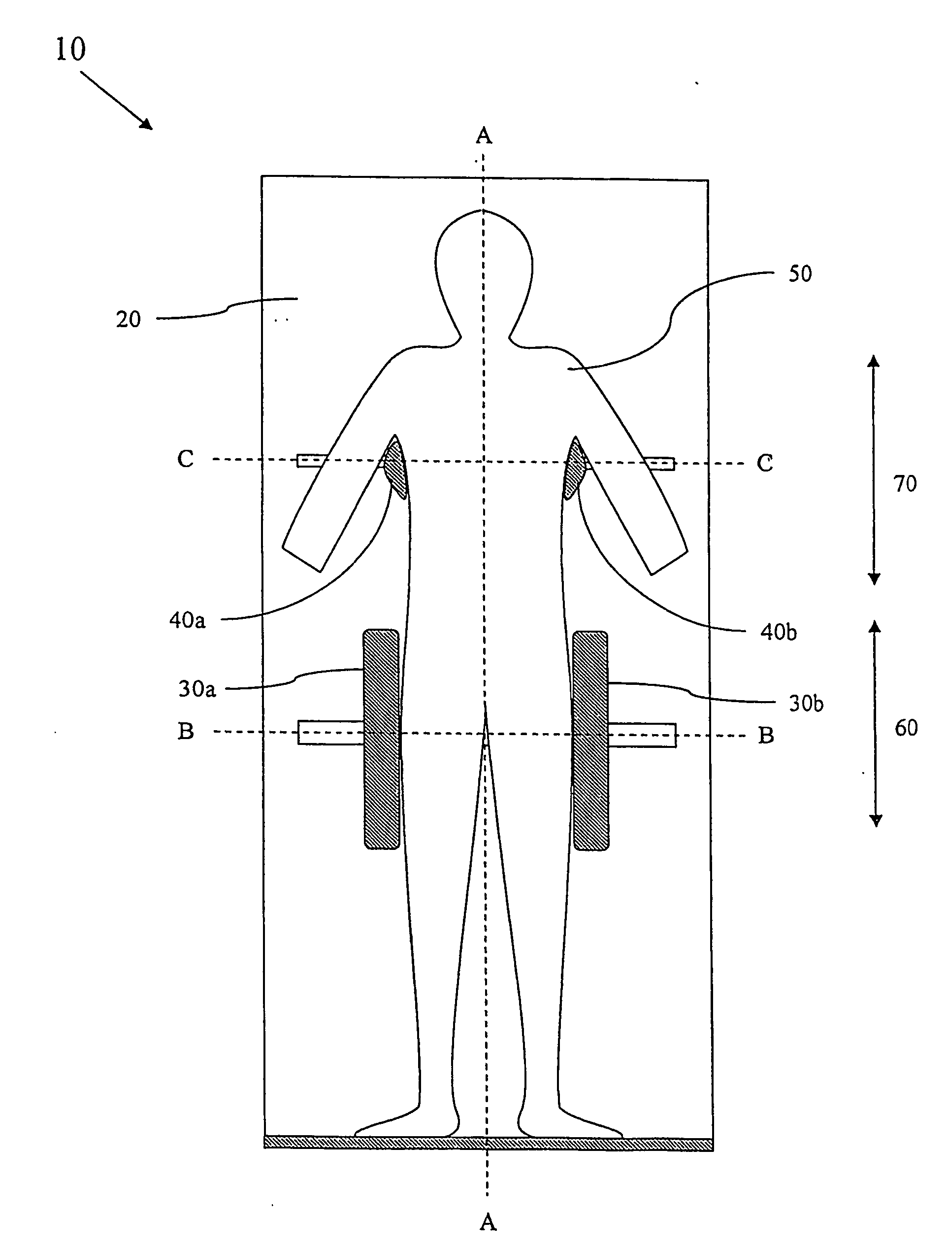
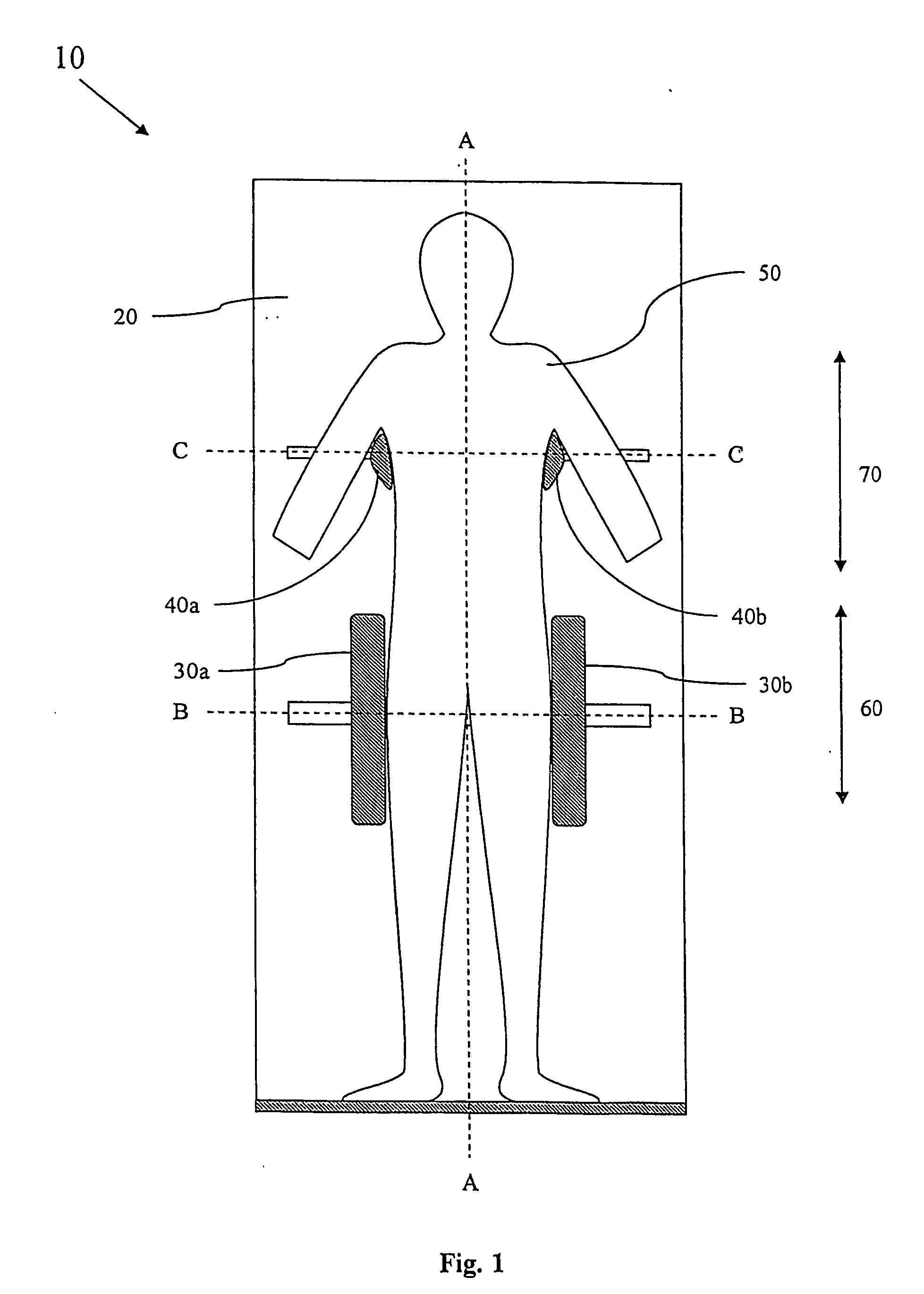
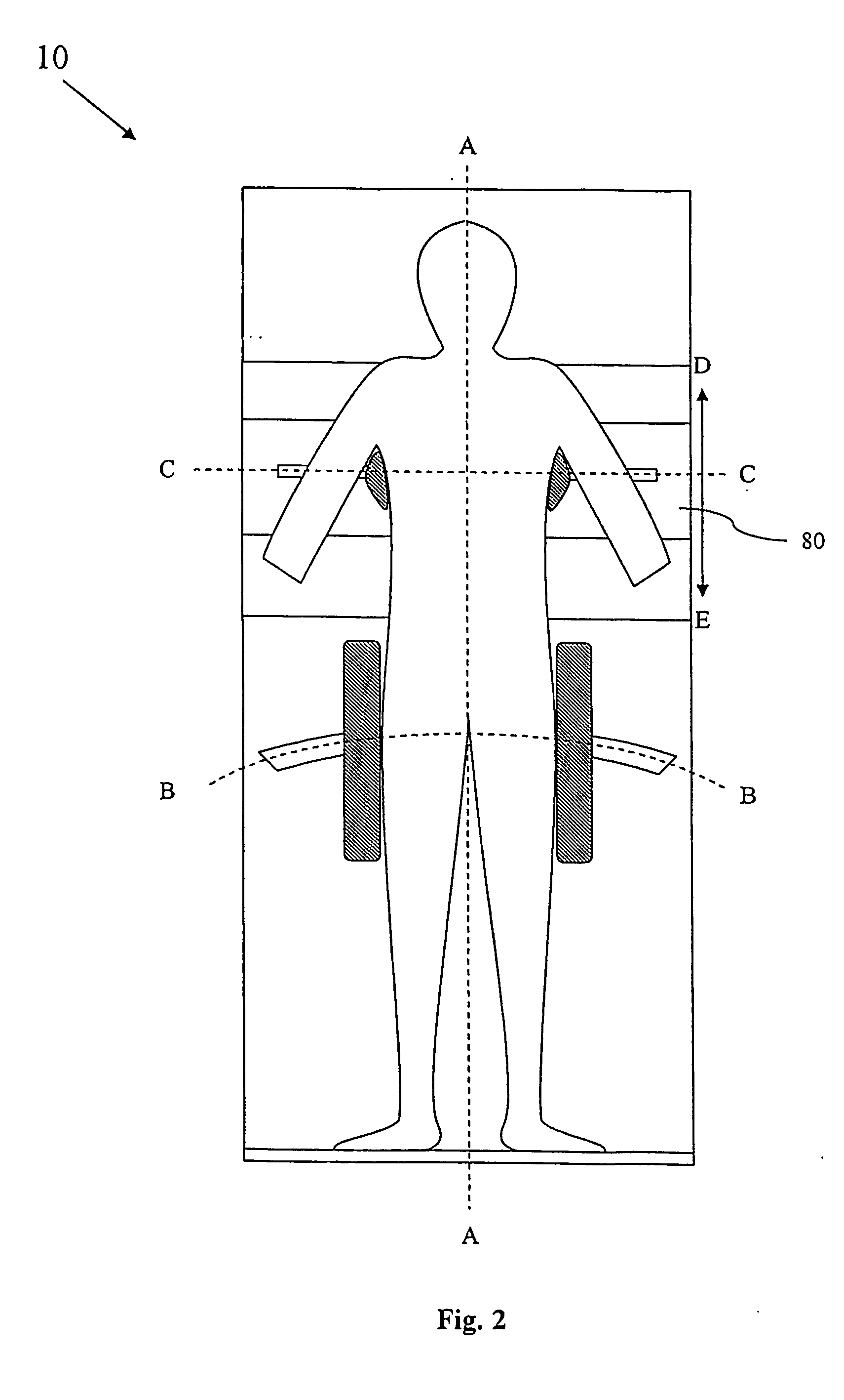
[0021]FIG. 1 schematically shows one embodiment of the patient repositioning device 10 according to the present invention. As discussed above, repositioning devices 10 of tilting type presents a large number of advantages compared to other prior art repositioning devices, but the known devices of tilting type tend to be complicated to use.

[0022] Like the device disclosed in U.S. Pat. No. 5,983,424, the repositioning device 10 according the present invention comprises a patient supporting panel 20 and at least one pair of laterally (along the broken lines B-B and C-C respectively) adjustable side support structures 30a,b, 40a,b for sideways supporting a patient 50 on the supporting panel 20. But in order to achieve quick and reliable centering of the patient 50 relative the panel 20, each pair of side support structures 30a,b, 40a,b are linked by a link arrangement, which is described below, so that they automatically are centered about a longitudinal axis A-A of the supporting pane...


PUM


Abstract

Patient repositioning device (10) comprising, a patient supporting panel (20), at least one pair of laterally adjustable side support structures (30a,b, 40a,b) for sideways supporting a patient (50) on the supporting panel (20). To achieve repeatable repositioning of a patient body (50) each pair of side support structures (30a,b, 40a,b) are linked by a link arrangement ensuring that the side support structures (30a, b, 40a, b) automatically are centered about a longitudinal axis (A-A) of the supporting panel (20) indicating the centre of a patient (50) supported on the panel (20). There is also provided a method of repositioning a patient.

Description

[0001] The present invention relates to a patient repositioning device according to the preamble of claim 1 and a method of repositioning of a patient on a treatment or diagnostic table for radiological procedures according to the preamble of claim 17. BACKGROUND OF THE INVENTION [0002] In radiotherapy as well as in surgical operations, the possibility of locating the actual disease volume with great accuracy is essential for the success of the treatment. To minimize the risk for geographical miss in the treatment, the correct target volume in the body is identified in diagnostic devices such as X-ray systems, Computerized Tomography devices (CT), Gamma Cameras, Nuclear Magnetic Resonance units (NMR or just MR). The responsible physician specifies the target volume to be treated by contours in the diagnostic images and these images are then used for planning of the treatment by manual or computerized methods. The therapeutic procedure, Radiation Therapy or Surgery, is then performed...

Claims


Application Information

Patent Timeline
IPC IPC(8): A61B6/08H05G1/00A47B13/00A61BA61B6/04
CPCA61B6/0421
Inventor NASLUND, INGEMARLAX, INGMAR
Owner ONCOLOG MEDICAL QA
Learn More