
Contaminant-reactive geocomposite mat and method of manufacture and use

a geocomposite mat and contaminant-reactive technology, applied in the field of contaminant-reactive geocomposite mat and method of manufacture and use, can solve the problem of restricting the aqueous flow through the mat by pressur

Inactive Publication Date: 2006-12-21
AMCOL INTERNATIONAL CORPORATION
View PDF6 Cites 25 Cited by
  • Summary
  • Abstract
  • Description
  • Claims
  • Application Information

AI Technical Summary

Benefits of technology

The geocomposite provides secure, uniform distribution of contaminant-reactive materials throughout its thickness, preventing leakage and maintaining effective contaminant reaction without the need for periodic replacement, while allowing aqueous flow and flexibility in application.

Problems solved by technology

One of the major problems encountered with the use of reactive mats for controlling or confining contaminated materials, or in controlling or preventing leaching of contaminants from sediments and preventing the contaminants from entering ground water supplies or from traversing through a lake or ocean soil interface into the lake or ocean, is in the ability to provide a transportable mat having a sufficient volume or thickness of reactive material so that the mat provides very long term protection without the necessity of periodic replacement.
Another issue with the '945 and '166 mats is that when water swellable sodium bentonite clay is utilized, with or without the reactive material, when the sodium bentonite clay swells, the resulting swell pressure restricts the aqueous flow through the mat.

Method used


Image

  • Contaminant-reactive geocomposite mat and method of manufacture and use
  • Contaminant-reactive geocomposite mat and method of manufacture and use
  • Contaminant-reactive geocomposite mat and method of manufacture and use

Examples


Embodiment Construction

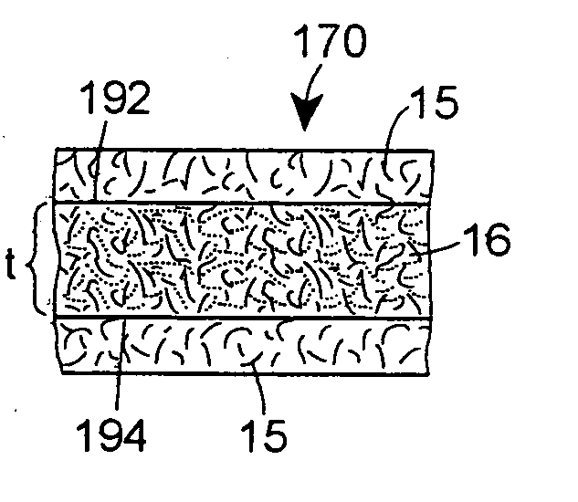
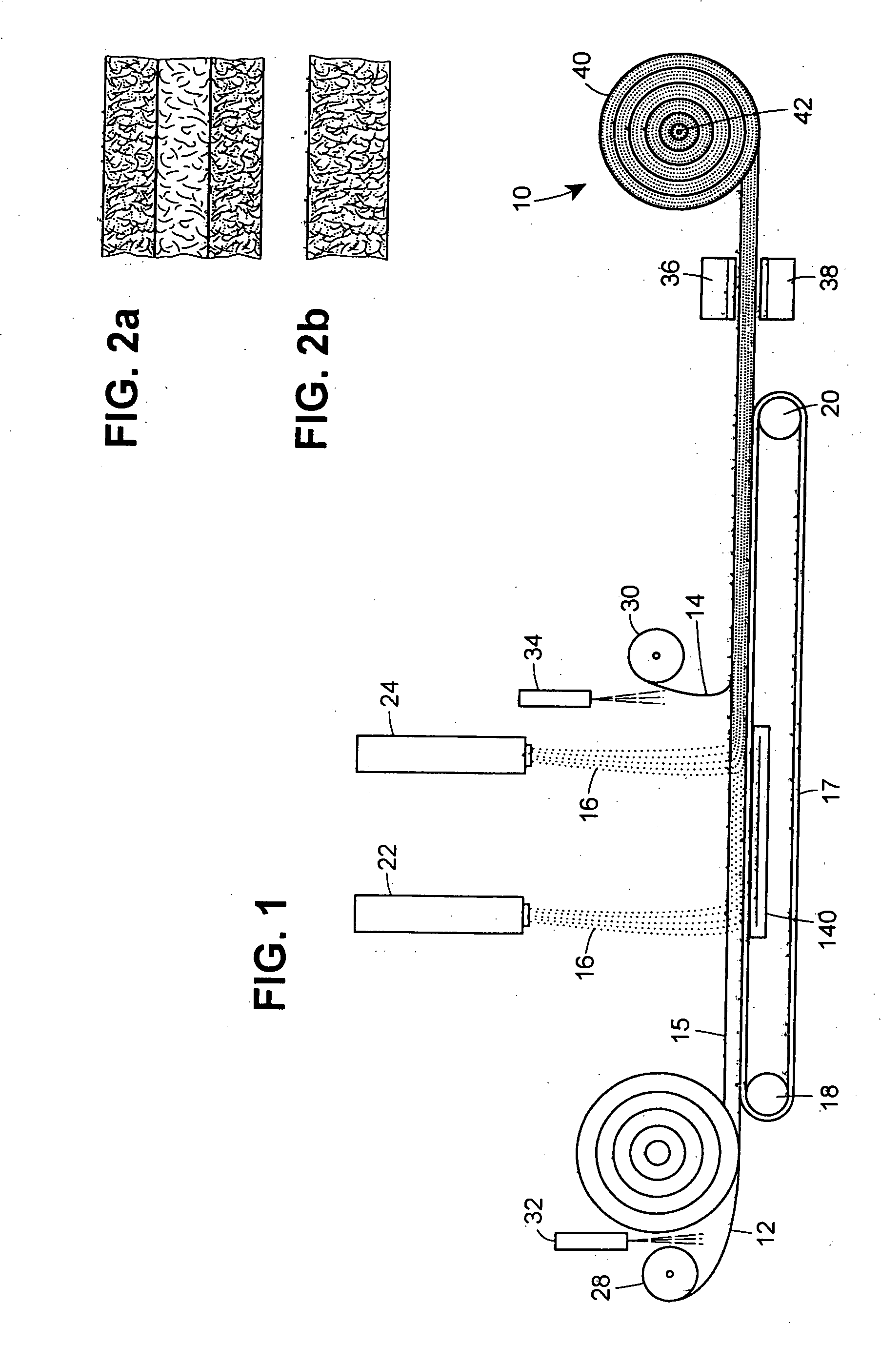
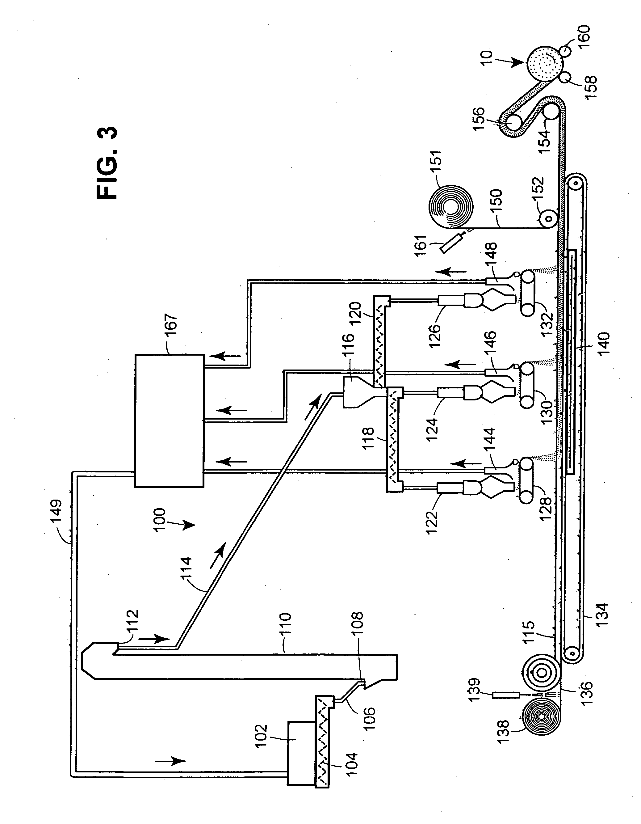
[0020] Turning now to FIG. 1, there is shown a schematic diagram for manufacturing the geocomposite articles 10 described herein, including many optional features any one or more of which can be included in the manufacturing process to provide various characteristics and properties to the geocomposite articles.

[0021] The geocomposite article 10 is manufactured to include a layer of woven or non-woven liquid-permeable sheet material 12 and 14 on both major exterior surfaces; various reinforcing material can be included within the interior and / or exterior of the article to provide structural reinforcement or to provide various degrees of article rigidity; portions of the high loft geotextile 15, along its upper and / or lower major surfaces can be left with low concentrations of, or without, a powdered or granular material so that a portion of the article is very porous to allow for venting of gases captured by the article from below; and powdered or granular materials such as a contam...


PUM

PropertyMeasurementUnit
thicknessaaaaaaaaaa
thicknessaaaaaaaaaa
sizeaaaaaaaaaa

Abstract

Reactive geocomposite mats, and their method of manufacture, for treating contaminants in soil or water that allow the passage of essentially non-contaminated water therethrough. The geocomposite mat includes a pre-formed woven or non-woven geotextile, having a thickness of about 6 mm to about 200 mm, and having, a porosity sufficient to receive a powdered or granular contaminant-reactive material, contaminant-sorptive material, or a contaminant-neutralizing material (hereinafter collectively referred to as “contaminant-reactant material” or “contaminant-reactive material”) throughout its thickness, or in any portion of the thickness across its entire major surface(s). The powdered or granular contaminant-reactive material is disposed within the pores of the previously formed, high loft geotextile mat to surround the fibers, e.g., by vacuum or vibrating the high loft mat while in contact with the contaminant-reactive material to allow the powdered or granular contaminant-reactive material to flow by gravity into the pores of the previously formed geotextile and vibrational forces. Liquid-permeable cover sheets are adhered to the upper and lower major surfaces of the filled geotextile to prevent the powdered or granular material from escaping from the geotextile during transportation and installation.

Description

FIELD OF THE INVENTION [0001] The present invention is directed to a reactive geocomposite for controlling or preventing the further spread of contaminants in soil or water. More particularly, the geocomposite described herein includes a reactive core formed from a high loft geotextile that is filled with a powdered or granular reactive material, such as activated carbon, coke breeze, peat moss, polymeric ion exchange resins, polymeric adsorbing resins; zero-valent iron, apatite, organophilic clay, zeolite, diatomaceous earth or mixtures thereof and having a liquid-permeable cover sheet attached to the upper and lower major surfaces of the filled geotextile. BACKGROUND AND PRIOR ART [0002] The prior art is replete with methods and articles used to confine or store a wide variety of environmental contaminants ranging from completely capping, in-situ, contaminated sediments that are left in-place in underwater environments; terrestrial landfills wherein dredged or otherwise collected ...

Claims


Application Information

Patent Timeline
Patent Type & Authority Applications(United States)
IPC IPC(8): B32B5/00A01K1/015B32B27/12D04H1/00B01D39/00B32B5/26D06N7/00E02D31/00
CPCB01D39/1623Y10T428/24B01D2239/0668B01D2239/0681B01D2239/10B09C1/002B09C1/08B32B5/26D04H3/00E02D17/202E02D31/004D06N3/0011D06N2205/10D06N2201/0254D06N2211/16D06N2201/0263D06N2201/02D06N2209/126Y10T156/1069B01D2239/0659Y10T428/249921Y10T428/31786Y10T442/659Y10T442/674Y10T442/676Y10T442/699B32B5/22D06N7/00B32B5/24B32B3/02B32B3/26B32B7/12B32B37/12B32B2262/0253B32B2264/10B32B2307/726
Inventor OLSTA, JAMES T.HORNADAY, CHARLES J.TRAUGER, ROBERT J.DARLINGTON, JERALD W. JR.
Owner AMCOL INTERNATIONAL CORPORATION
Learn More