Eureka AIR delivers breakthrough ideas for toughest innovation challenges, trusted by R&D personnel around the world.

Digital broadcasting transmission and reception devices and methods thereof

a digital broadcasting and transmission technology, applied in the field of digital broadcasting transmission and reception, can solve the problems of weak signal strength, dynamic multi-path interference, and inferior system reception performance in deteriorated channels, and achieve the effect of improving reception performan

Active Publication Date: 2006-12-21
SAMSUNG ELECTRONICS CO LTD
View PDF14 Cites 121 Cited by
  • Summary
  • Abstract
  • Description
  • Claims
  • Application Information

AI Technical Summary

Benefits of technology

[0016] The present invention has been developed in order to address the above drawbacks and other problems associated with the conventional arrangement. An aspect of the present invention is to provide digital broadcasting transmission and reception devices that provide a sub-channel in which robust data and a supplementary reference signal will be transmitted so that a reception performance can be improved in a dynamic multi environment, and methods thereof.

Problems solved by technology

Accordingly, this system has inferior reception performance in a deteriorated channel, particularly, in a Doppler fading channel.
As described above, major problems of the conventional VSB system, which transmits and receives data over the air, are performance degradation in weak signal strength and dynamic multi-path interference.
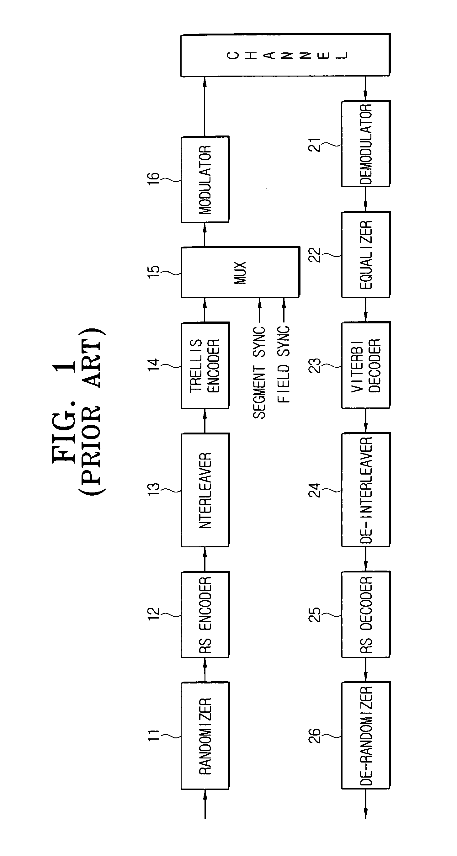
The conventional ATSC VSB system illustrated in FIG. 1 transmits a dual transport stream including robust data; however, it cannot be expected to improve degraded reception performance in a multi-path channel when the conventional VSB system transmits normal data stream.
Additionally, there is no big improvement in the reception performance regarding robust stream in a multi-path environment.

Method used


Image

  • Digital broadcasting transmission and reception devices and methods thereof
  • Digital broadcasting transmission and reception devices and methods thereof
  • Digital broadcasting transmission and reception devices and methods thereof

Examples


Embodiment Construction

[0051] Exemplary embodiments of the present invention will be described in detail with reference to the annexed drawings. In the drawings, the same elements are denoted by the same reference numerals throughout the drawings. In the following description, detailed descriptions of known functions and configurations incorporated herein have been omitted for conciseness and clarity.

[0052]FIG. 3 is a block diagram of a digital broadcasting transmission device according to an exemplary embodiment of the present invention.

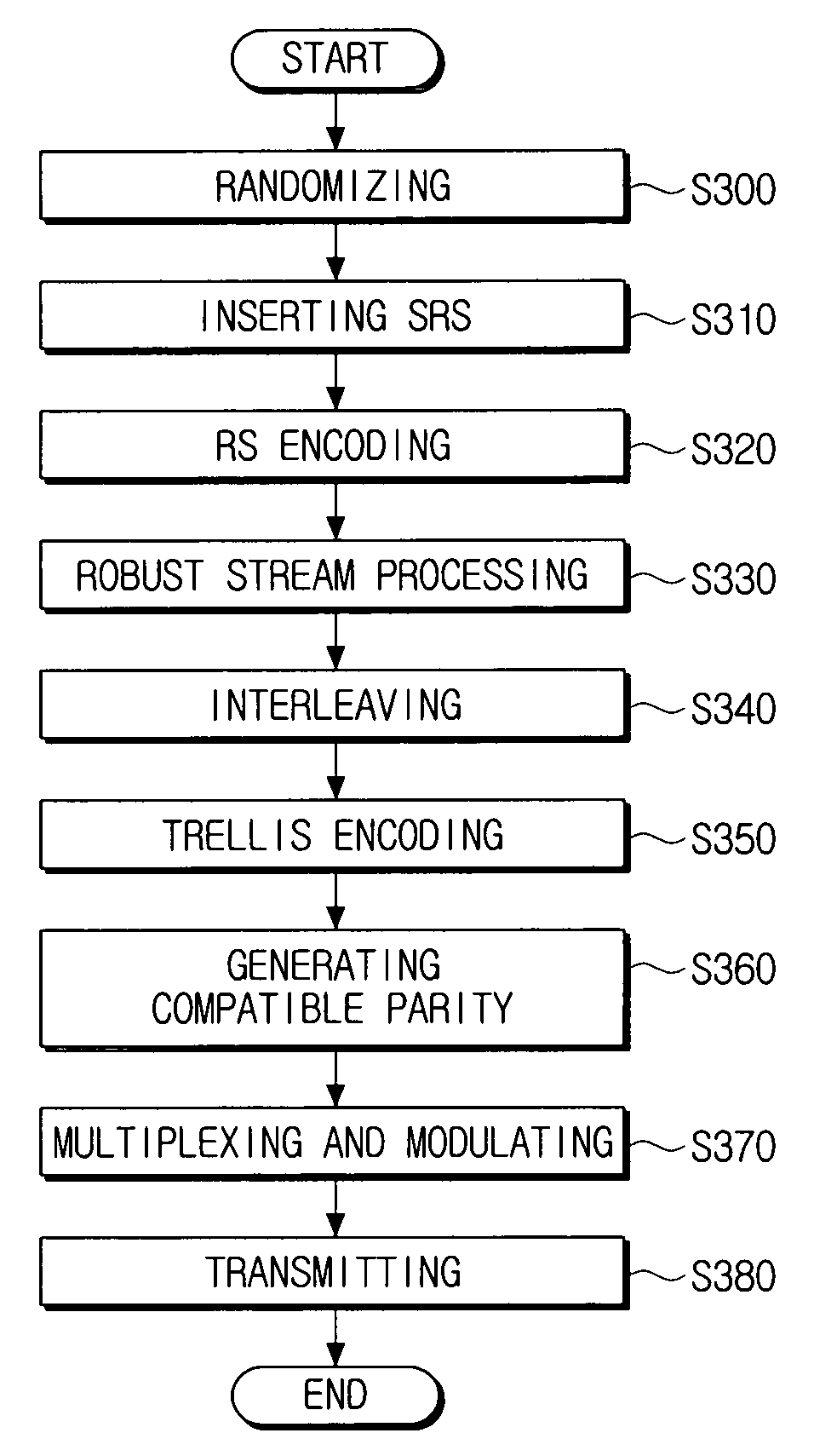
[0053] Referring to FIG. 3, a digital broadcasting transmission device according to an exemplary embodiment of the present invention comprises a randomizer 101, a stuff byte controller 103, a supplementary reference signal inserter 105, an RS encoder 107, a signal controller 109, a robust processor 111, an interleaver 113, a compatible parity generator 115, a trellis encoder 117, a main Mux 119, and a modulator 121.

[0054] The randomizer 101 randomizes a dual transport ...


PUM

PropertyMeasurementUnit
strengthaaaaaaaaaa
timeaaaaaaaaaa
sizeaaaaaaaaaa

Abstract

Digital broadcasting transmission and reception devices and methods thereof are provided. The digital broadcasting transmission device includes a randomizer which randomizes a dual transport stream including a normal stream and a robust stream, a supplementary reference signal inserter which inserts a certain supplementary reference signal into a stuffing region included in the randomized dual transport stream, a Reed-Solomon (RS) encoder which adds a parity into a parity region included in the dual transport stream, a robust processor which configures a new dual transport stream by convolution-encoding the robust stream among the dual transport stream, an interleaver which interleaves the configured dual transport stream, a trellis encoder which trellis-encode the interleaved dual transport stream, and a modulator which transmits the trellis-encoded dual transport stream. Accordingly, a sub-channel can be provided in which the robust data and the supplementary reference signal will be transmitted.

Description

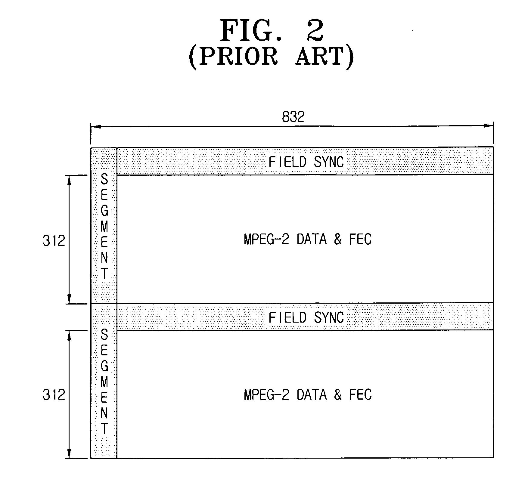
[0001] This application claims priority from U.S. Provisional Patent Application No. 60 / 664,637 filed on Mar. 24, 2005, in the United States Patent and Trademark Office, and from Korean Patent Application No. 10-2006-0021613 filed on Mar. 8, 2006 in the Korean Intellectual Property Office, the disclosure of which is incorporated herein by reference.BACKGROUND OF THE INVENTION [0002] 1. Field of the Invention [0003] Apparatuses and methods consistent with the present invention relate to digital broadcasting transmission and reception, and more particularly to digital broadcasting transmission and reception devices that can provide a sub-channel to transmit and receive robust stream, and methods thereof. [0004] 2. Description of the Related Art [0005] Advanced Television System Committee (ATSC) Vestigial Sideband (VSB) system, which is an American terrestrial digital broadcasting system, is a single carrier system, and uses field sync with 312 segment units. Accordingly, this system h...

Claims


Application Information

Patent Timeline
Patent Type & Authority Applications(United States)
IPC IPC(8): H04L27/04H04N19/89
CPCH03M13/256H03M13/2936H03M13/356H03M13/6538H04L1/0071H04N21/4382H04L1/006H04L1/0065H04L1/007H04N21/2383B01D33/01B01D33/801
Inventor KIM, JOON-SOOPARK, EUI-JUNCHANG, YONG-DEOKJEONG, HAE-JOO
Owner SAMSUNG ELECTRONICS CO LTD
Why Eureka
Eureka Blog
Learn More