
Optical Filters and Method of Manufacturing the Same

a technology of optical filters and filters, applied in the field of filters with light filtering, can solve the problems of multi-layer coating sunglasses glasses with dielectric mirrors having an objectionable image, and multi-layer coating sunglasses also suffering from angle sensitivity effects

Inactive Publication Date: 2006-12-21
COLORLINK
View PDF18 Cites 8 Cited by
  • Summary
  • Abstract
  • Description
  • Claims
  • Application Information

AI Technical Summary

Benefits of technology

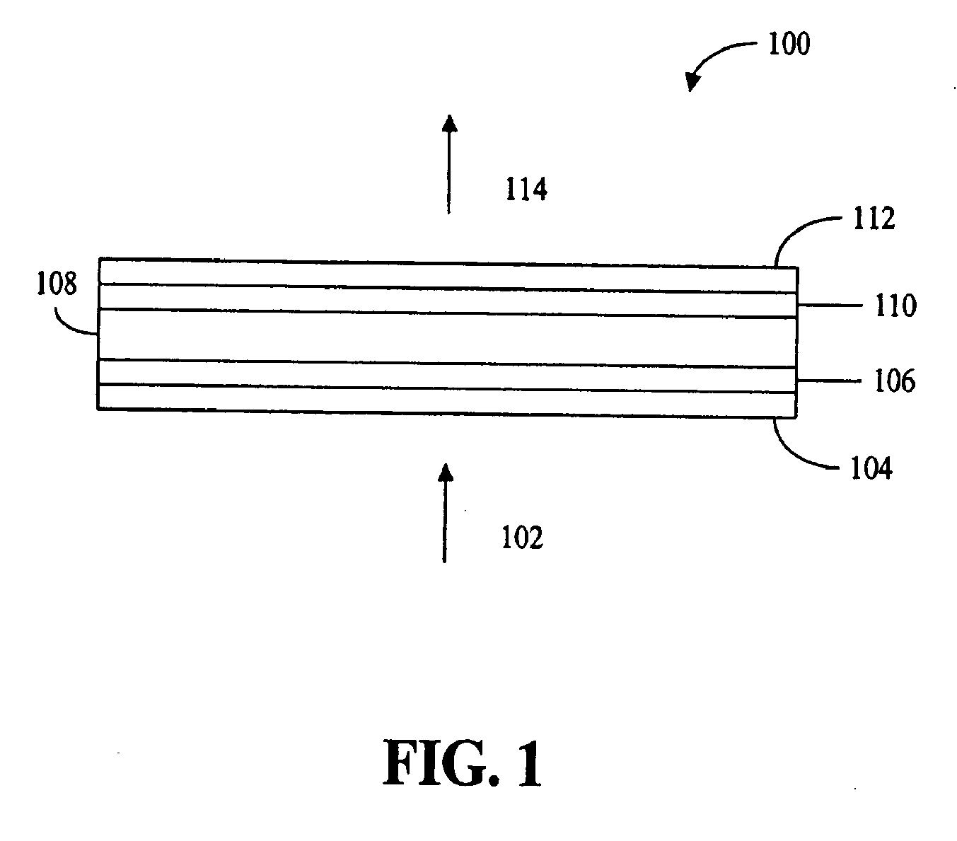
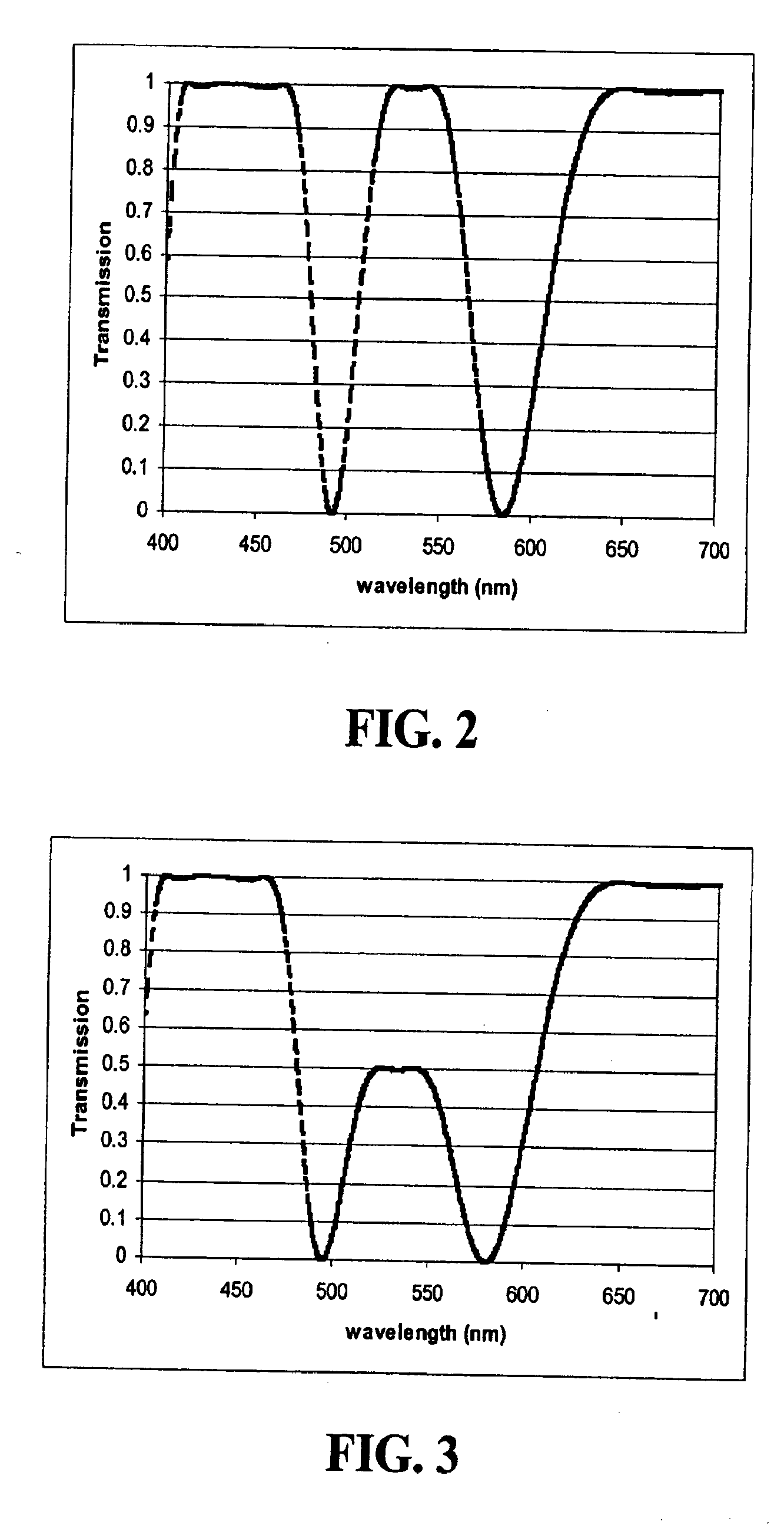
The patent describes an optical filter that can be used in eyewear to filter light in different ways. The filter can improve color vision, protect the eyes from harmful light rays, or enhance human or animal vision. The filter includes an input polarizing element, an output polarizing element, and a retarder stack between them. The retarder stack filters light to enhance the appearance of colors or protect the eyes from harmful light rays. The filter can also be designed to filter specific bands of light or to enhance the saturation of colored objects. The method of filtering light involves polarizing the input light, rotating its polarization, and analyzing the rotated light. The filter has a specific light transmittance at certain wavelengths. Overall, the optical filter can provide improved vision and protect the eyes from harmful light.

Problems solved by technology

Unfortunately, rare-earth doped sunglasses have a fixed spectrum and multi-layer coating sunglasses may have an objectionable image due to light reflection.
Multi-layer sunglasses may also suffer from angle sensitivity effects.
As with other multiple layer coatings, glasses with dielectric mirrors may have an objectionable image due to light reflection and may suffer from angle sensitivity effects.

Method used


Image

  • Optical Filters and Method of Manufacturing the Same
  • Optical Filters and Method of Manufacturing the Same
  • Optical Filters and Method of Manufacturing the Same

Examples


Embodiment Construction

[0016] The selective filtering of light by polarization interference may be used to enhance human or animal vision and / or protect the eyes from harmful light rays. For example, such filtering may be used in sunglasses, color corrective eyewear or protective eyewear. The selective filtering of incident light may provide any desired spectral transmission (including visible light and light not visible to the human or animal eye) and is performed by a pair of polarizing elements that sandwich a retarder stack. The filtering structure may be formed by multi-layer polarizing structures and may be formed by fabricating sheet laminates that are die cut to form inexpensive laminates. The laminates may be flat or curved in one (e.g., wrap-around) or more dimensions.

[0017] One exemplary embodiment of the present invention provides an optical filter for eyewear with a laminated polarizing filter having a spectral transmission that enhances color vision via polarization interference. For exampl...


PUM

PropertyMeasurementUnit
wavelengthaaaaaaaaaa

Abstract

The selective filtering of light by polarization interference may be used to enhance vision and / or protect eyes from harmful light rays. For example, such filtering may be used in sunglasses, color corrective eyewear or protective eyewear. The selective filtering of incident light may provide any desired spectral transmission (including visible light and light not visible to the eye) and is performed by a pair of polarizing elements that sandwich a retarder stack. The filtering structure may be formed by multi-layer polarizing structures and may be formed by fabricating sheet laminates that are die cut to form inexpensive laminates. The laminates may be flat or curved in one (e.g., wrap-around) or more dimensions.

Description

PRIORITY CLAIM AND RELATED APPLICATION [0001] This application is a continuation of U.S. Pat. App. Ser. No. 10 / 655,858, filed Sep. 5, 2003, which claims priority under 35 U.S.C. § 119(e) to U.S. Provisional App. entitled “Filter for Enhancing Human Vision and / or Protecting the Eyes and Method of Making a Filter,” Ser. No. 60 / 408,754 filed Sep. 6, 2002, having Gary D. Sharp, as inventor, and having as assignee ColorLink, Inc., the assignee of the present application. The provisional application is incorporated herein by reference in its entirety for all purposes.FIELD OF THE INVENTION [0002] The present invention relates generally to filters with light filtering to enhance vision and / or protect the eyes and to a method of making the filters. BACKGROUND [0003] Sunglasses, which suppress glare, may be made with films having moderate neutral polarizing efficiency. Sunglasses, which selectively filter transmitted light, may be made with multilayer thin-films, diffractive structures that ...

Claims


Application Information

Patent Timeline
Patent Type & Authority Applications(United States)
IPC IPC(8): G02F1/1347G02B5/30G02B27/28
CPCG02B27/288G02B5/3041
Inventor SHARP, GARY D.
Owner COLORLINK
Learn More