
Portable terminal device

Inactive Publication Date: 2006-12-21
FUJITSU TOSHIBA MOBILE COMM LTD
View PDF7 Cites 64 Cited by
  • Summary
  • Abstract
  • Description
  • Claims
  • Application Information

AI Technical Summary

Benefits of technology

[0009] It is accordingly the object of the present invention to provide a portable terminal device which, without placing any added burden on the user, can provide the same operability to an input device as an input operation target even if the terminal device takes any posture direction.

Problems solved by technology

This places added operational burden on the user.

Method used


Image

  • Portable terminal device
  • Portable terminal device
  • Portable terminal device

Examples


Embodiment Construction

[0027] With reference to the drawing explanation will be given below about an embodiment of the present invention.

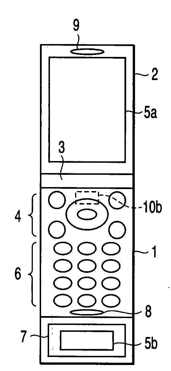
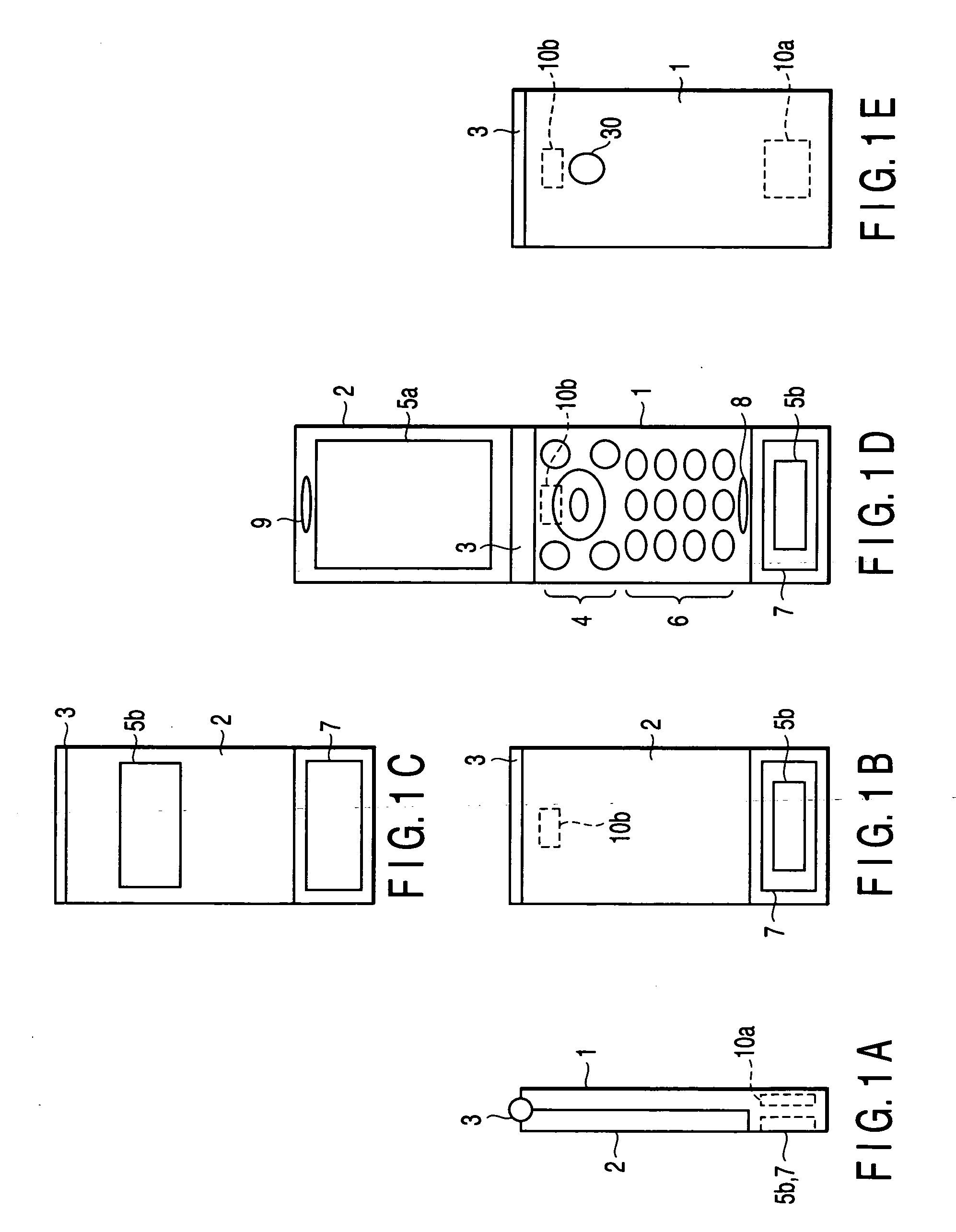
[0028]FIGS. 1A, 1B, 1C, 1D, 1E show an outer appearance of a mobile phone relating to the embodiment of the present invention. This mobile phone is so-called a folding type portable terminal device comprising an upper casing 1, a lower casing 2 and a hinging section (a coupling mechanism) 3 through which the upper and lower casings are openable and closable relative to each other. It is to be noted that the upper casing 1 and lower casing 2 are referred to as an upper shell 1 and lower shell 2.

[0029] On a front surface of the first shell 1 shown in FIG. 1C are provided an input device (function keys 4, dial keys 6), a sub-display 5b, a touch pad 7, and an aperture section 8 for a microphone. The function keys 4 include a plurality of keys to which specific functions are imparted, such as a select key, a transmit key, an end key, a schedule key, a clear key and a cursor...


PUM


Abstract

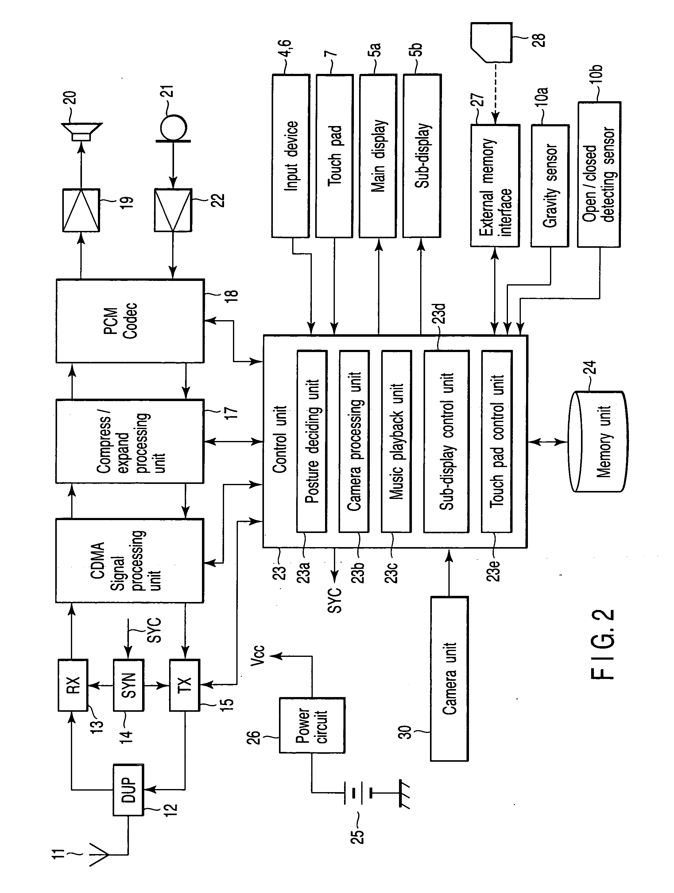
A portable terminal device comprises an input device configured to receive an input operation on a plurality of positions, the input device allocating a function to be executed to the plurality of positions by an input operation, a sensor configured to detect a posture of the portable terminal device, and a control unit configured to allow the function to be changed according to the posture of the portable terminal device detected by the sensor.

Description

CROSS-REFERENCE TO RELATED APPLICATIONS [0001] This application is based upon and claims the benefit of priority from prior Japanese Patent Application No. 2005-178031, filed Jun. 17, 2005, the entire contents of which are incorporated herein by reference. BACKGROUND OF THE INVENTION [0002] 1. Field of the Invention [0003] The present invention relates to a portable terminal device such as a mobile phone, a personal digital assistant (PDA), etc. [0004] 2. Description of the Related Art [0005] Conventionally, a portable terminal device represented by a mobile phone is so constructed as to, when the direction (posture) of the terminal device is changed, allow a corresponding change to be done on an array of keys (for example, Jpn. Pat. Appln. KOKAI Publication No. 2005-12493). In the portable terminal device of this KOKAI Publication, a vertical direction key matrix corresponding to key switches and character information for vertical use and a horizontal direction key matrix correspon...

Claims


Application Information

Patent Timeline
IPC IPC(8): G09G5/00G06F3/038
CPCG06F1/1616G06F1/165G06F1/1671G06F1/1677H04M1/0245G06F1/1686G06F1/1692G06F2200/1614G06F1/1684
Inventor SHINTOME, JUNICHI
Owner FUJITSU TOSHIBA MOBILE COMM LTD
Learn More