
Medical stapler

Active Publication Date: 2006-12-14
COOK MEDICAL TECH LLC
View PDF40 Cites 34 Cited by
  • Summary
  • Abstract
  • Description
  • Claims
  • Application Information

AI Technical Summary

Benefits of technology

[0007] A medical device is disclosed herein that may provide advantages over medical staplers known in the art. The medical device of the present disclosure may be suitable for use in endoscopic procedures, for example, and may allow a physician to approximate opposing tissues with one hand while operating an endoscope with the other.

Problems solved by technology

However, properly deploying stainless steel staples proved difficult because of the substantial amount of force required to deform stainless steel staples into a closed position.
Despite this effort, surgical staplers continue to suffer from one or more of the following drawbacks.
Surgical staplers are relatively heavy and bulky; they are expensive because of their complex inner workings; they often obstruct the target location for the staple; and each stapler is intended for a narrow range of procedures.
Despite the significant advance of using SMA surgical staples instead of stainless steel surgical staples, the staplers used to deliver SMA surgical staples suffer from one or more of the following drawbacks.
First, such staplers are unsuitable for use in endoscopic procedures.
That is, such staplers are not deliverable through the working channel of an endoscope.
Accordingly, endoscopically (or laparascopically) created incisions cannot be closed with traditional SMA staplers.
Second, these staplers require that both tines of a staple be simultaneously inserted into the opposing tissues of an incision.
This can be particularly limiting during endoscopic procedures in which the physician needs one hand to operate the endoscope.
Moreover, since both tines enter the opposing sides of the tissue simultaneously, the tines cannot be used to gather and approximate the opposing tissues.

Method used


Image

  • Medical stapler
  • Medical stapler
  • Medical stapler

Examples


Embodiment Construction

[0025] The invention is described with reference to the drawings in which like elements are referred to by like numerals. The relationship and functioning of the various elements of this invention are better understood by the following detailed description. However, the embodiments of this invention as described below are by way of example only, and the invention is not limited to the embodiments illustrated in the drawings. It should also be understood that the drawings are not to scale and in certain instances details have been omitted which are not necessary for an understanding of the present invention, such as conventional details of fabrication and assembly.

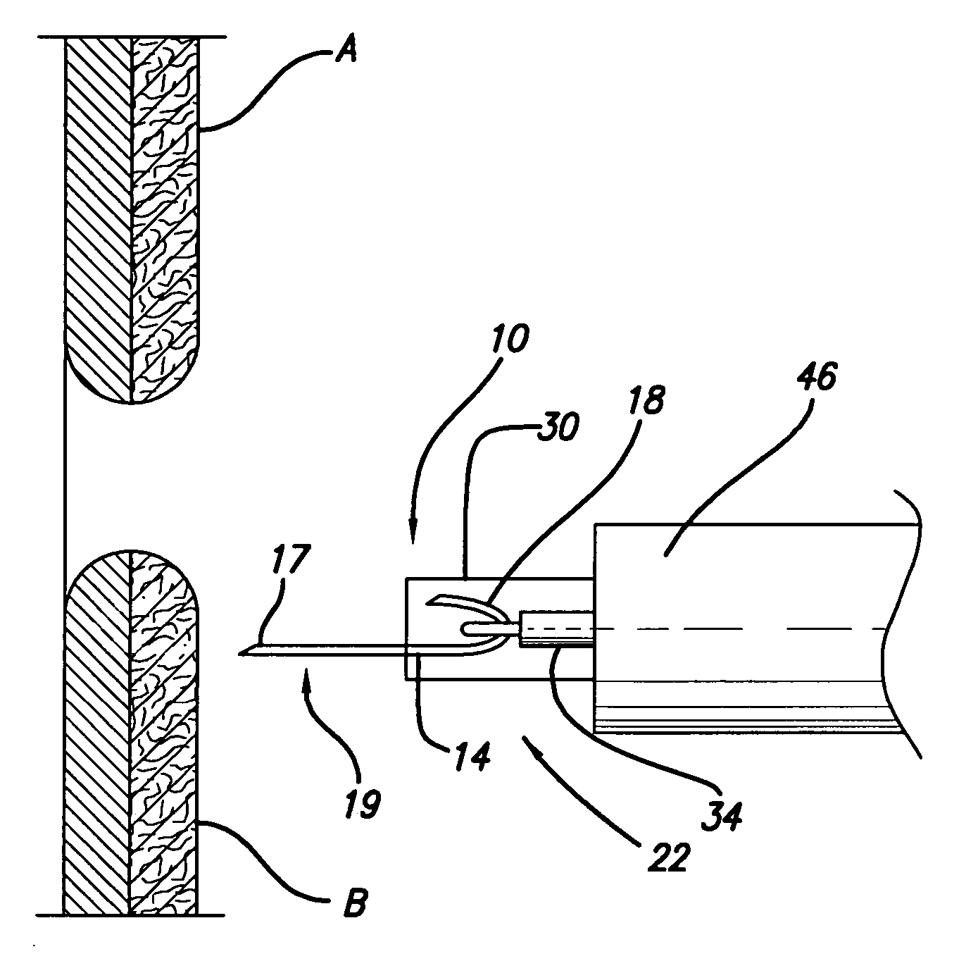
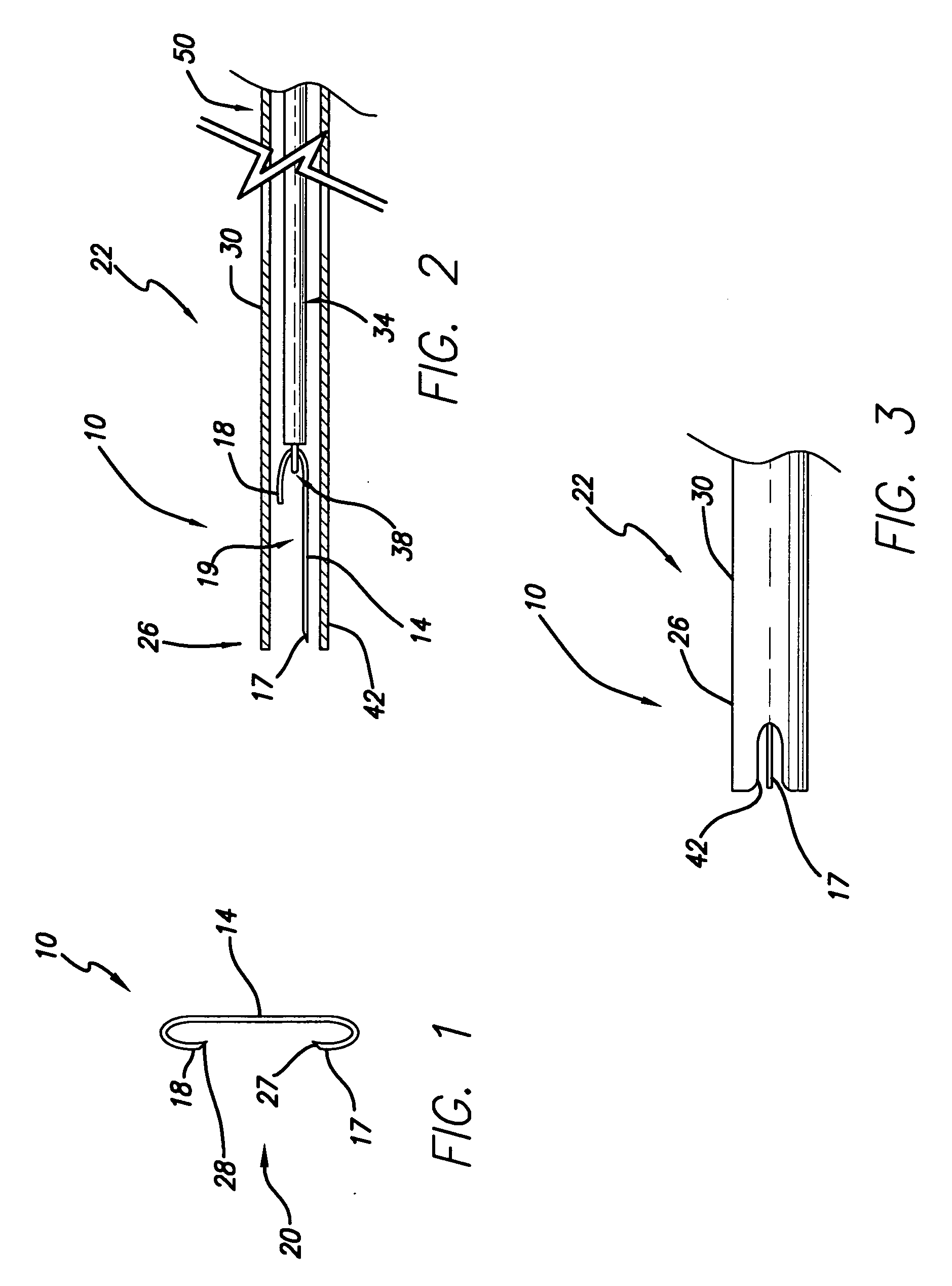
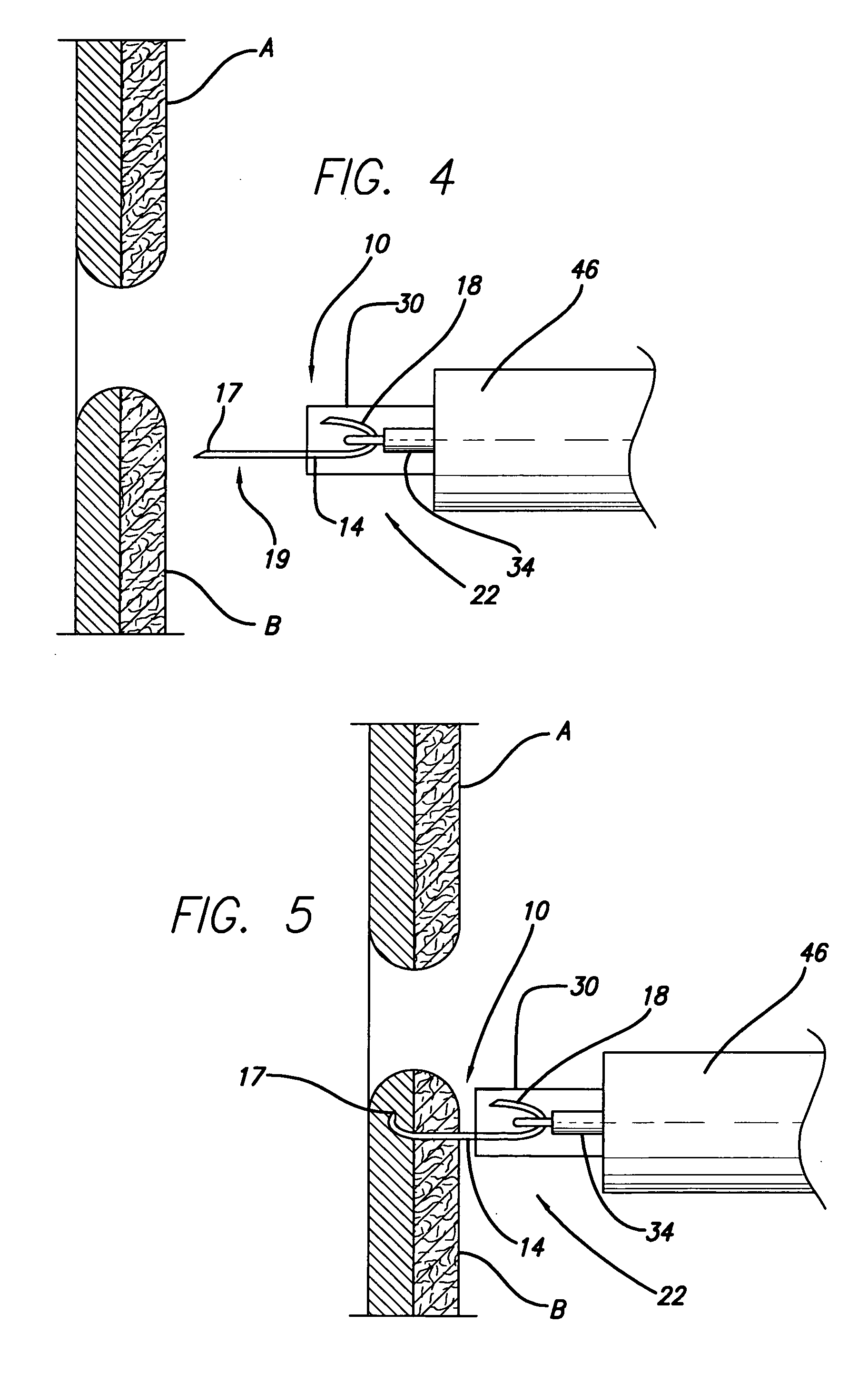
[0026] Referring now to the Figures, there is shown in FIG. 1 a staple 10 having a bridge 14 connecting a first tine 17 and a second tine 18. The first and second tines 17, 18 may include first and second ends 27, 28 that are adapted to penetrate tissue. The first and second ends 27, 28 may facilitate entry of the first an...


PUM

PropertyMeasurementUnit
Temperatureaaaaaaaaaa

Abstract

A stapler for delivering a staple formed from a shape memory material is disclosed. The staple includes a first tine and a second tine connected by a bridge. The staple may be disposed within the stapler in an open position with the first tine distal of the second tine. The stapler is configured to sequentially deliver the first tine and the second tine, respectively, to opposing body tissues. The stapler includes an elongate shaft (e.g., a catheter) having a working lumen and a control mechanism for delivering the staple. A drive cable extends along the working lumen of the elongate shaft. Upon warming up to a temperature at or above a transformation temperature of the shape memory material, the staple may assume a closed position, thus drawing together opposing body tissues and closing an incision.

Description

[0001] This application claims the benefit of U.S. Provisional Patent Application No. 60 / 689,589, filed Jun. 10, 2005, which is incorporated by reference herein in its entirety.TECHNICAL FIELD [0002] This disclosure generally relates to medical devices, and particularly to surgical staples and devices for delivering surgical staples. BACKGROUND [0003] Surgical stapling is commonly used to close surgical incisions. Surgical stapling benefits the patient by reducing the amount of time the patient is under anesthesia. It also benefits physicians by eliminating much of the time and energy that was previously spent suturing surgical incisions with traditional needle and silk, polymer, or gut thread. As a result, surgical stapling has become the procedure of choice for incision closure, especially when confronting large incisions or wounds. [0004] Conventional staples used in surgical stapling initially were formed from stainless steel. However, properly deploying stainless steel staples ...

Claims


Application Information

Patent Timeline
IPC IPC(8): A61B17/08
CPCA61B17/064A61B17/0644A61B2017/081A61B2017/00867A61B17/0682
Inventor SURTI, VIHAR C.
Owner COOK MEDICAL TECH LLC
Learn More