Shaft coupler

a shaft and coupler technology, applied in the direction of couplings, fastening means, rod connections, etc., can solve the problems of large size and length of the coupler, difficulty in proper insertion and securing, and substantial amount of time taken to screw the couplers in place, etc., to achieve the effect of resistance to movemen

Inactive Publication Date: 2006-12-14
XTECH INDS INT
View PDF10 Cites 20 Cited by
  • Summary
  • Abstract
  • Description
  • Claims
  • Application Information

AI Technical Summary

Benefits of technology

[0011] The present invention is a shaft coupler having two complementary bodies that may be joined together to form a coupling. Each body is designed to be fixedly attached to the end of a shaft. Each coupler body has one or more curved flanges that mate to corresponding flanges of the other coupler body. The two coupler bodies are engaged together and rotated so that the end surfaces of the two corresponding flanges come in flush contact with each other. This forms a void next to the mated flanges of the coupler bodies. One or more locking blocks are then inserted into the void to prevent the coupler bodies from uncoupling and becoming unsecured. A locking block is attached to an interior segment of the coupler body by a fastener such that the sides of the locking block come in flush contact with the sides of the coupler bodies when the block is attached. The coupler bodies are fixedly attached due to the flush mating of all the faces of the flanges of one coupler body to the complementary faces of the flanges of the other coupler body. The engaged coupler bodies are resistant to movement with respect to each other in any direction, including rotationally. The engaged coupler bodies therefore serve to rigidly fix the ends of the shafts together, end to end, to further the purposes of the user.

Problems solved by technology

While these couplers secure two shafts together, a substantial amount of time is taken to screw the couplers in place.
This can be difficult if the shaft is of a large size or bulky.
Another problem with conventional threaded connectors, is that threads can become worn, especially if cross threaded, making proper insertion and securing difficult.
One dilemma with this device is that the slidably mounted locking bolt makes the size and length of the coupler greater, and possibly difficult to use if in a confined space.
In addition, the mechanism for securing the locking pin is likely not reliable enough for various operations as the laterally mounted pin is only held in place by the pressure of the bolt pushing against it.
While the device secures the shafts together, it has disadvantages such as the inability to allow a passageway through the shaft due to the bulk of the coupling.
In addition, the bolt securing the sleeve element of the coupler comes in direct contact with the force of the couplers, and therefore may fatigue or lessen over time.
While this locking method secures electrical cables together to further prevent a disconnection, the means for locking of this device are not rigid enough to withstand forces upon a shaft used in a structural context.
While a seal is used on the device disclosed in this patent, it is not capable of keeping pressure within a passageway within the shaft or other body to which the coupler is connected.

Method used


Image

  • Shaft coupler
  • Shaft coupler
  • Shaft coupler

Examples


Embodiment Construction

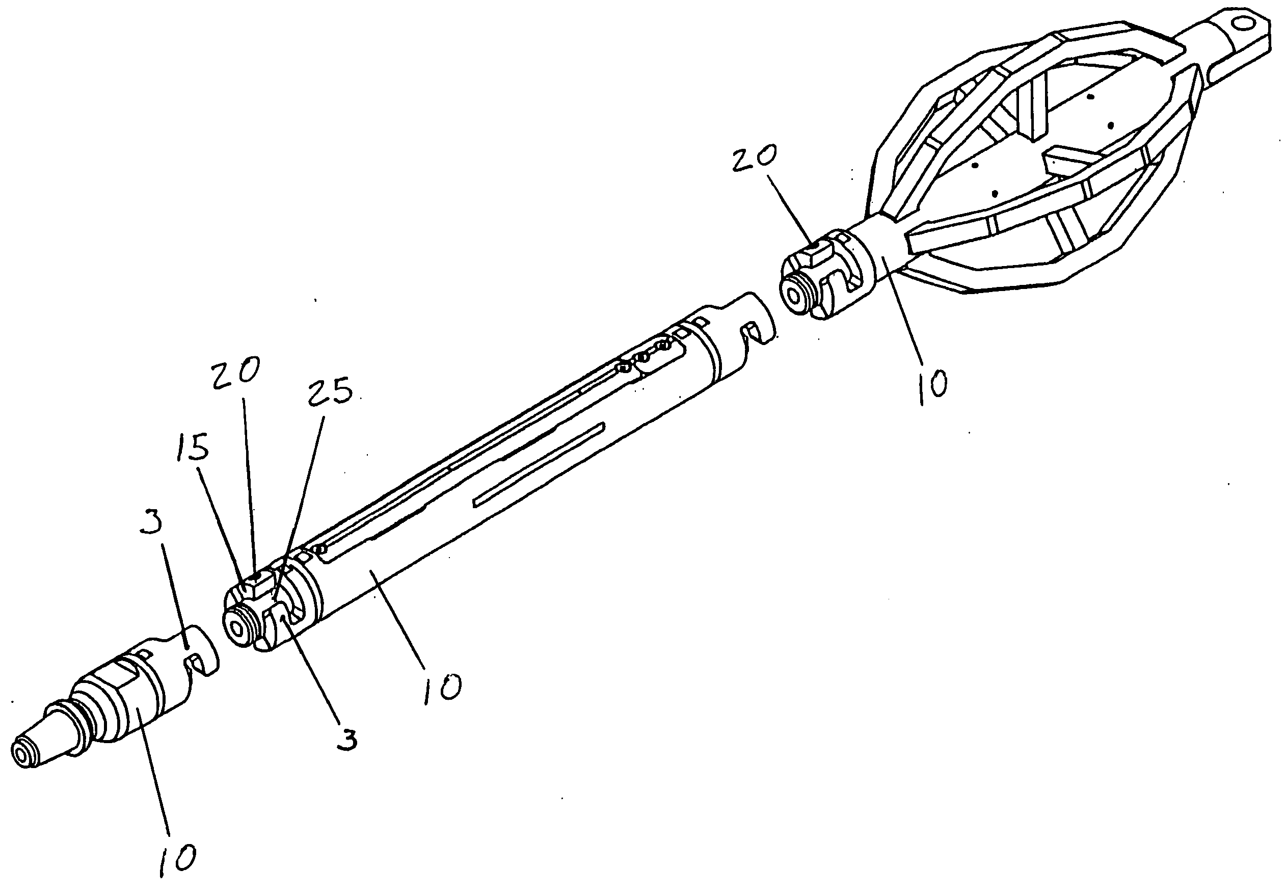
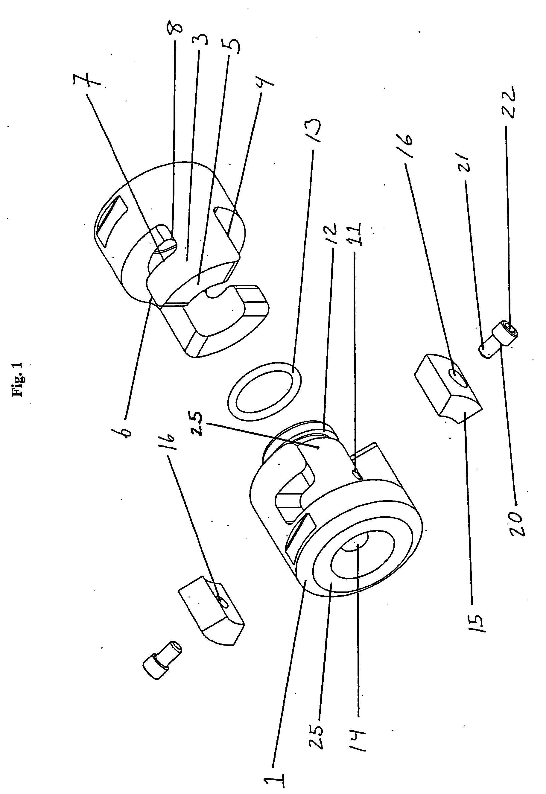
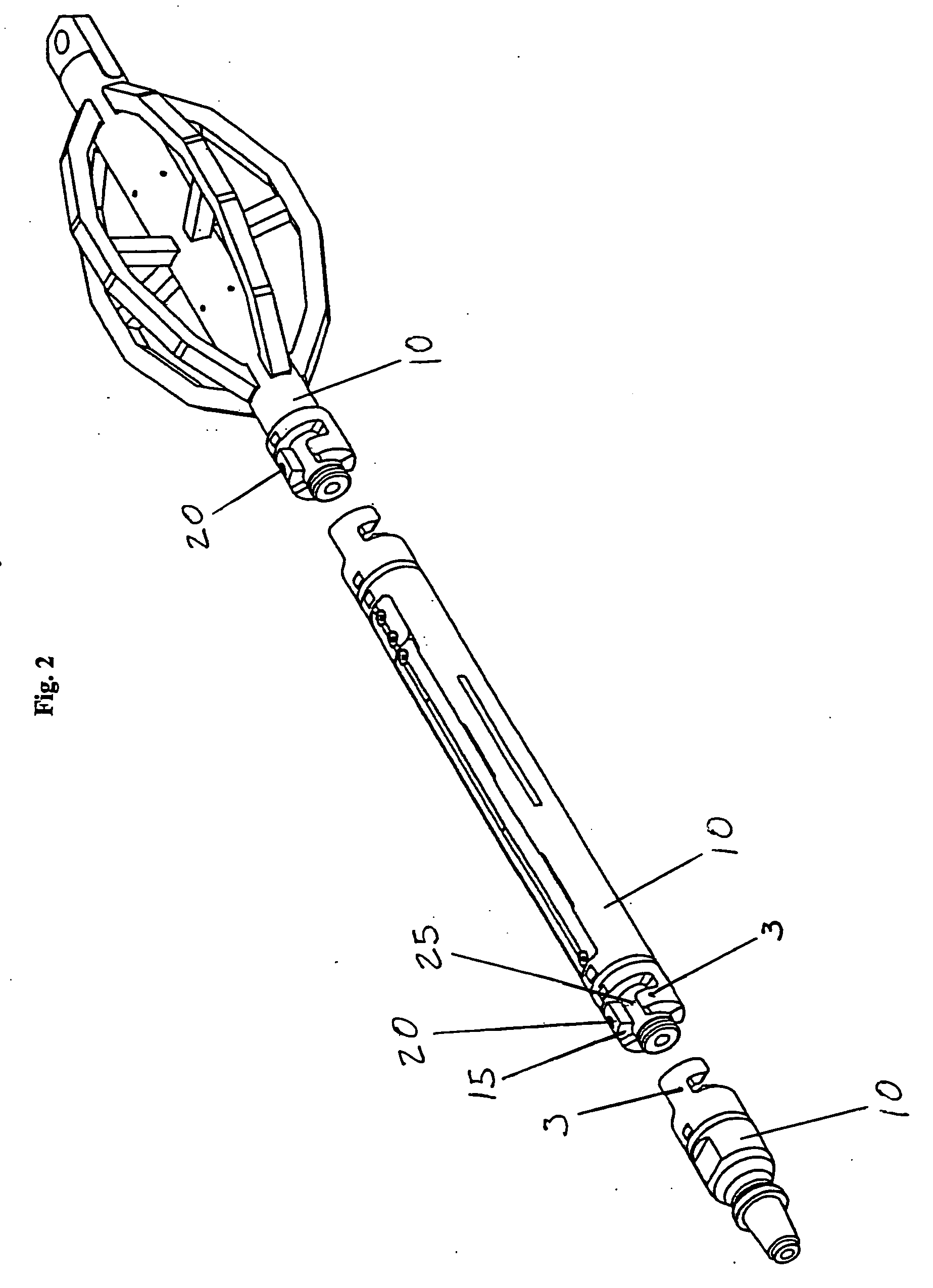
[0029] Referring to the drawings wherein like reference characters designate like or corresponding parts throughout the several views, and referring particularly to FIG. 1, it is seen that the coupler invention includes two coupler bodies 1. The coupler bodies 1 are each attached to the ends of separate shafts 10. An interior cylinder 25 extends past the end of the first coupler body. Each coupler body 1 has one or more flanges 3 that are in the general shape of an inverted “L.” Each flange has a rear vertical face 4, upper lateral face 5, extended vertical face 6, lower lateral face 7, and indented vertical face 8. The faces of the flange contact and mate with the complementary faces of the flange of the other coupling body.

[0030] To attach two shafts by use of the coupler, the user inserts the flanges of the coupler bodies into the void next to the one or more flanges of the other coupler body. The coupler bodies are then rotated until the extended vertical face 6 of each flange ...


PUM


Abstract

The present invention is a shaft coupler having two complementary bodies that may be joined together to form a coupling. Each body is designed to be fixedly attached to the end of a shaft and has one or more curved flanges that mate to corresponding flanges of another coupler body. The two coupler bodies are engaged together and rotated so that the surfaces of the two corresponding flanges are flush. This forms a void next to the mated flanges of the coupler bodies. One or more locking blocks are then inserted into the void to prevent the coupled bodies from untwisting, thereby securing the couplers in place and the shafts together. The locking block is attached to an interior segment of shaft by a fastener and the sides of the locking block come in flush contact with the sides of the coupler bodies and flanges thereof when attached. The coupler serves to rigidly fix the ends of the shafts together, end to end, to further the purposes of the user. The couplers are fixedly attached due to the mating of all the faces of the flanges of one coupler to the corresponding faces of the flanges of the other coupler body. The coupler is resistant to movement of the shafts with respect to each other in any direction including rotationally.

Description

[0001] This application claims the benefit of U.S. Provisional Patent Application No. 60 / 688,889 filed on Jun. 8, 2005, which is incorporated herein by this reference.BACKGROUND OF THE INVENTION [0002] 1. Field of the Invention [0003] The present invention relates to couplers, and more particularly to a unique non-threaded coupler for use in the secure connection of shafts in a linear orientation. [0004] 2. Description of the Prior Art [0005] Cylindrical shafts, shafts, hollow tubes and the like (shafts) are commonly used in a multitude of mechanical devices. Shafts are used for many purposes in mechanical devices. For example, shafts can be used as structural supports, conduits for other parts of the device, a moving component, or a combination thereof. In addition, hollow shafts can supply pressurized gases or liquids from one location to another. In this context, a shaft can be any object of any size, shape, or function. It is often necessary to securely connect two shafts togeth...

Claims


Application Information

Patent Timeline
Patent Type & Authority Applications(United States)
IPC IPC(8): F16B21/02
CPCF16B7/0426Y10T403/7005F16B7/20
Inventor ANTHONY, PAUL G.
Owner XTECH INDS INT
Why Eureka
Try Eureka