
Optical disc apparatus

Inactive Publication Date: 2006-12-14
FUNAI ELECTRIC CO LTD
View PDF6 Cites 5 Cited by
  • Summary
  • Abstract
  • Description
  • Claims
  • Application Information

AI Technical Summary

Benefits of technology

[0015] Only an outer tilt angle is measured when an optical disc is mounted. Thus, the optical disc apparatus allows a shortened mounting process time and enhances user-friendliness. Also, the optical disc apparatus allows tilt angle adjustments to be made according to an amount of warpage of an optical disc in an access position, without use of a tilt sensor, resulting in a reduced frequency of data recording errors or data reading errors, as well as in enhanced reliability and reduced manufacturing costs.

Problems solved by technology

However, the configuration as disclosed in JP 2002-260263A requires the separate tilt sensor and leads to increased manufacturing costs.
Thus, the prior art apparatuses employing the fixed tilt angle has the following inherent problem.
The apparatuses cannot properly adjust the tilt angle according to amount of disc warpage in an access position, thereby causing a high frequency of data recording / reading errors.
However, the method requires a longer time to execute a mounting process, thereby rendering the apparatus less user-friendly.

Method used


Image

  • Optical disc apparatus
  • Optical disc apparatus
  • Optical disc apparatus

Examples


Embodiment Construction

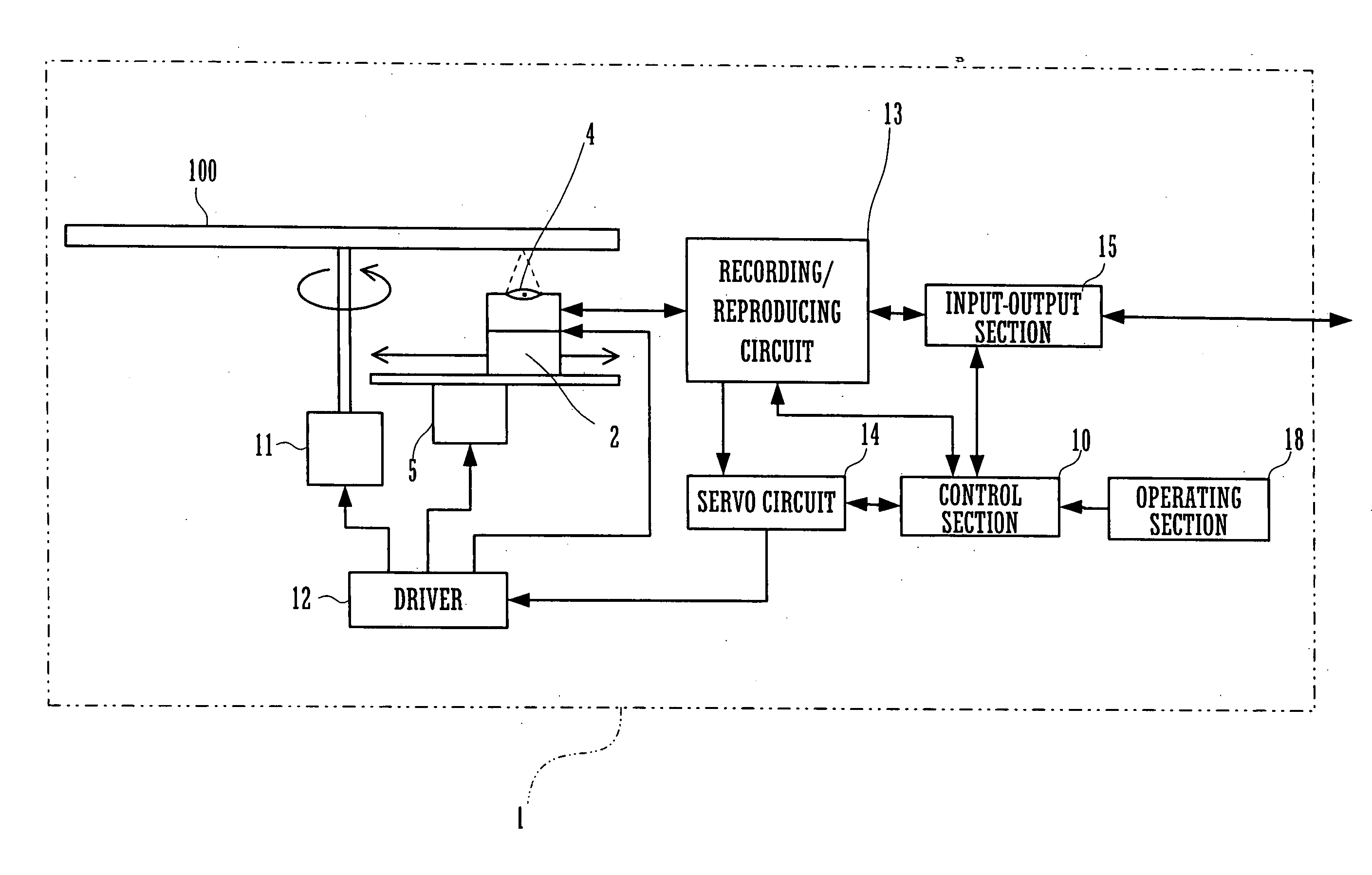
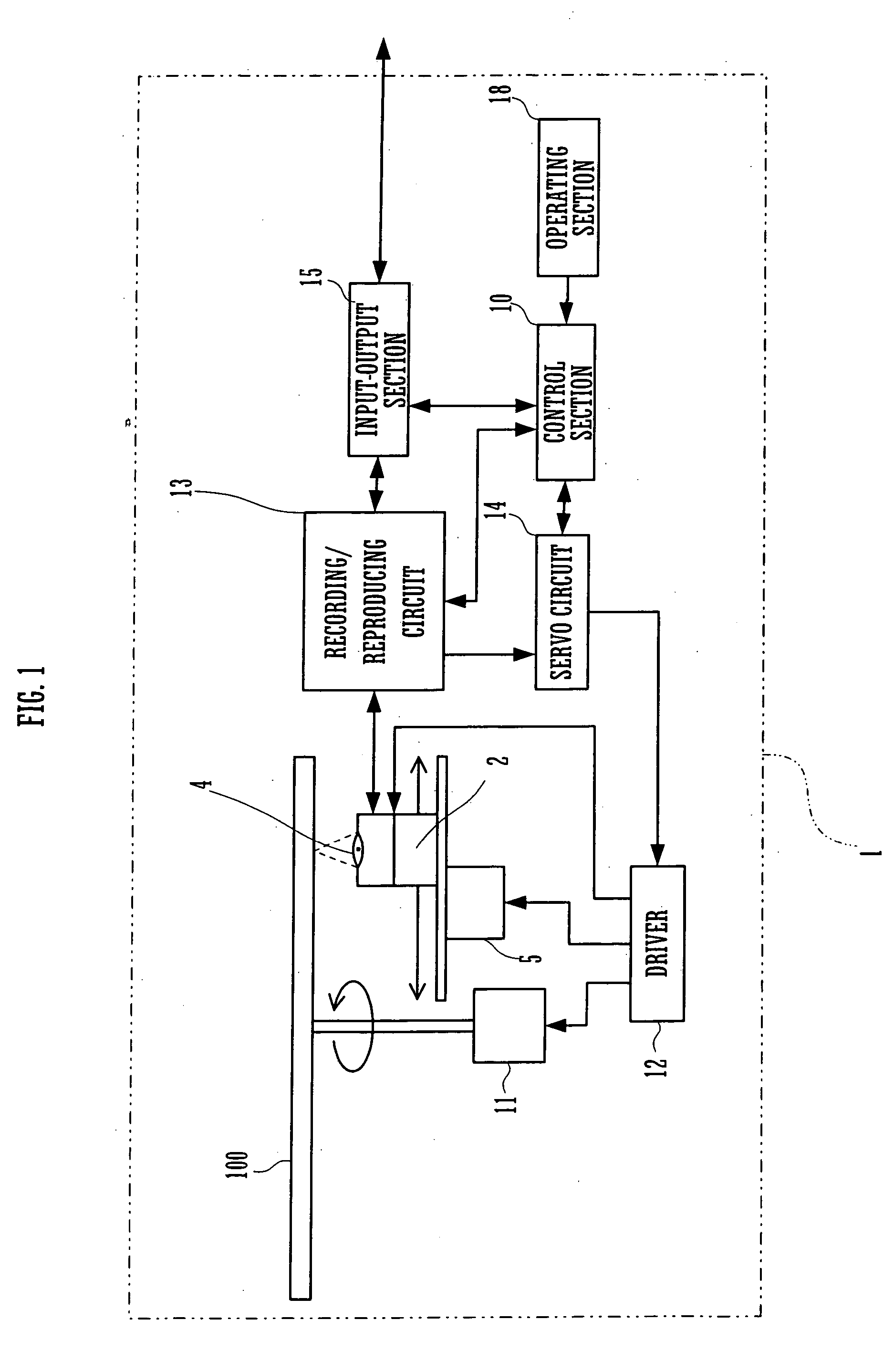
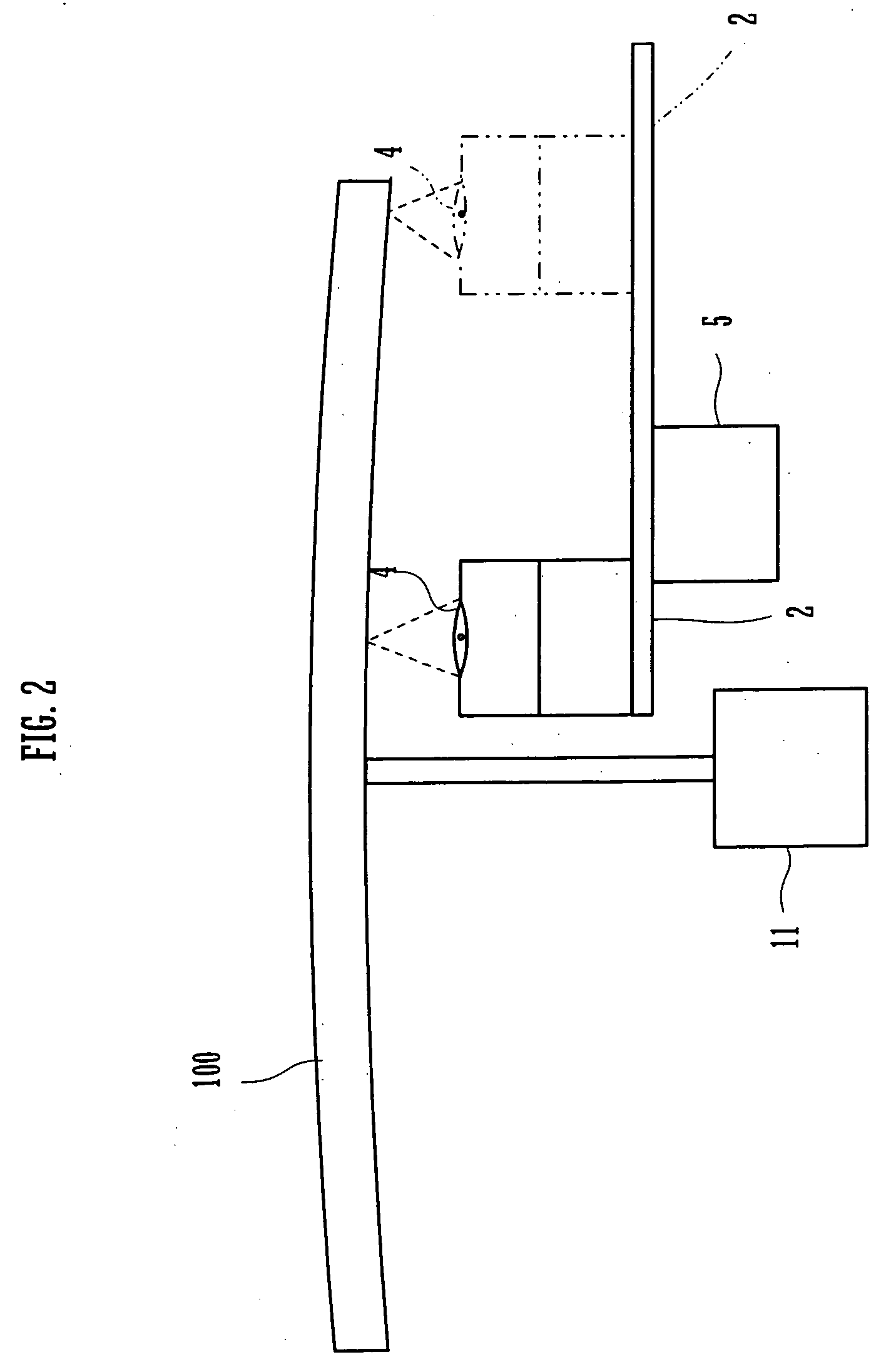
[0022]FIG. 1 is a block diagram for illustrating a configuration of an optical disc apparatus according to an embodiment of the invention. FIG. .2 is a schematic diagram for illustrating a construction of the optical disc apparatus. A control section 10 has overall control over an optical disc apparatus 1. The apparatus 1 includes a pickup assembly 2. The assembly 2 focuses laser radiation onto an optical disc 100. The assembly 2 has a laser diode (LD), a photodiode (PD), and an objective lens 4. The LD serves as a light source to emit laser radiation toward the disc 100. The PD is used to detect light reflected by the disc 100. The lens 4 is used to focus the laser radiation onto a recorded surface of the disc 100. The assembly 2 also has a focusing actuator, a tracking actuator, and a tilting actuator. The focusing actuator moves the lens 4 close to, and away from, the disc 100. The tracking actuator moves the lens 4 along a radial direction of the disc 100. The tilting actuator t...


PUM


Abstract

When an optical disc is mounted therein, an optical disc apparatus measures a tilt angle of an objective lens for an outer radial position on the optical disc, i.e., an outer tilt angle. Based on the outer tilt angle as measured and a preset inner tilt angle, the apparatus calculates a relationship between radial positions on the optical disc and tilt angles corresponding to the respective radial positions. In recording or reading data on or from the optical disc, the apparatus tilts the objective lens, according to the calculated relationship, at a tilt angle corresponding to a data recording position or a data reading position.

Description

CROSS REFERENCE [0001] This Non provisional application claims priority under 35 U.S.C.§119(a) on patent application No. 2005-150852 filed in Japan on May 24, 2005, the entire contents of which are hereby incorporated by reference. BACKGROUND OF THE INVENTION [0002] The invention relates to an optical disc apparatus adapted to record data on optical discs, such as compact discs (CDs) or digital versatile discs (DVDs), or retrieve data stored on such discs. [0003] There have been proposed optical disc apparatuses provided with a tilt angle adjusting mechanism that allows laser radiation from a pickup assembly to be incident on a recorded surface of an optical disc at right angles. Such apparatuses are disclosed in JP 2002-260263A and JP 2003-263764A. The tilt angle adjusting mechanism is provided for reducing negative influences of disc warpage on accuracy of recording or reading data on or from optical discs in order to improve the accuracy. The pickup assembly has an objective lens...

Claims


Application Information

Patent Timeline
IPC IPC(8): G11B7/00
CPCG11B7/0956G11B7/0945
Inventor ICHIHARA, KAZUO
Owner FUNAI ELECTRIC CO LTD
Learn More