
Communication system for communications carried over power lines

a communication system and power line technology, applied in the direction of electric variable regulation, process and machine control, instruments, etc., can solve the problems of power lines having to stop feeding electric power, physical separation of reception signals from transmission signals, and the inability to install relay amplifying devices easily, etc., to achieve the effect of large current capacity

Inactive Publication Date: 2006-12-14
MITSUBISHI ELECTRIC CORP
View PDF1 Cites 6 Cited by
  • Summary
  • Abstract
  • Description
  • Claims
  • Application Information

AI Technical Summary

Benefits of technology

[0007] The present invention has been made to solve the above problem, and an object of the present invention is therefore to provide a relay amplifying device of an over-power line communication system that can be installed without stopping power lines from feeding electric power by eliminating elements inserted in series with the power lines.
[0009] An over-power line communication system according to the present invention makes a relay amplifying device installable without stopping power lines from feeding electric power by eliminating from the relay amplifying device elements that are inserted in series with the power lines. Another effect is that the present invention is applicable to a power line that has a large current capacity.

Problems solved by technology

However, in over-power line communication systems which use power lines as transmission paths, it is difficult to separate reception signals from transmission signals physically.
However, inserting elements in series with power lines means that the power lines have to stop feeding electric power during installation of such a relay amplifying device.
Accordingly, this type of relay amplifying device cannot be installed easily.

Method used


Image

  • Communication system for communications carried over power lines
  • Communication system for communications carried over power lines
  • Communication system for communications carried over power lines

Examples


first embodiment

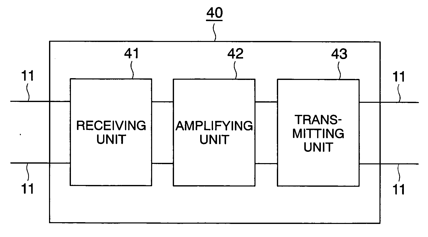
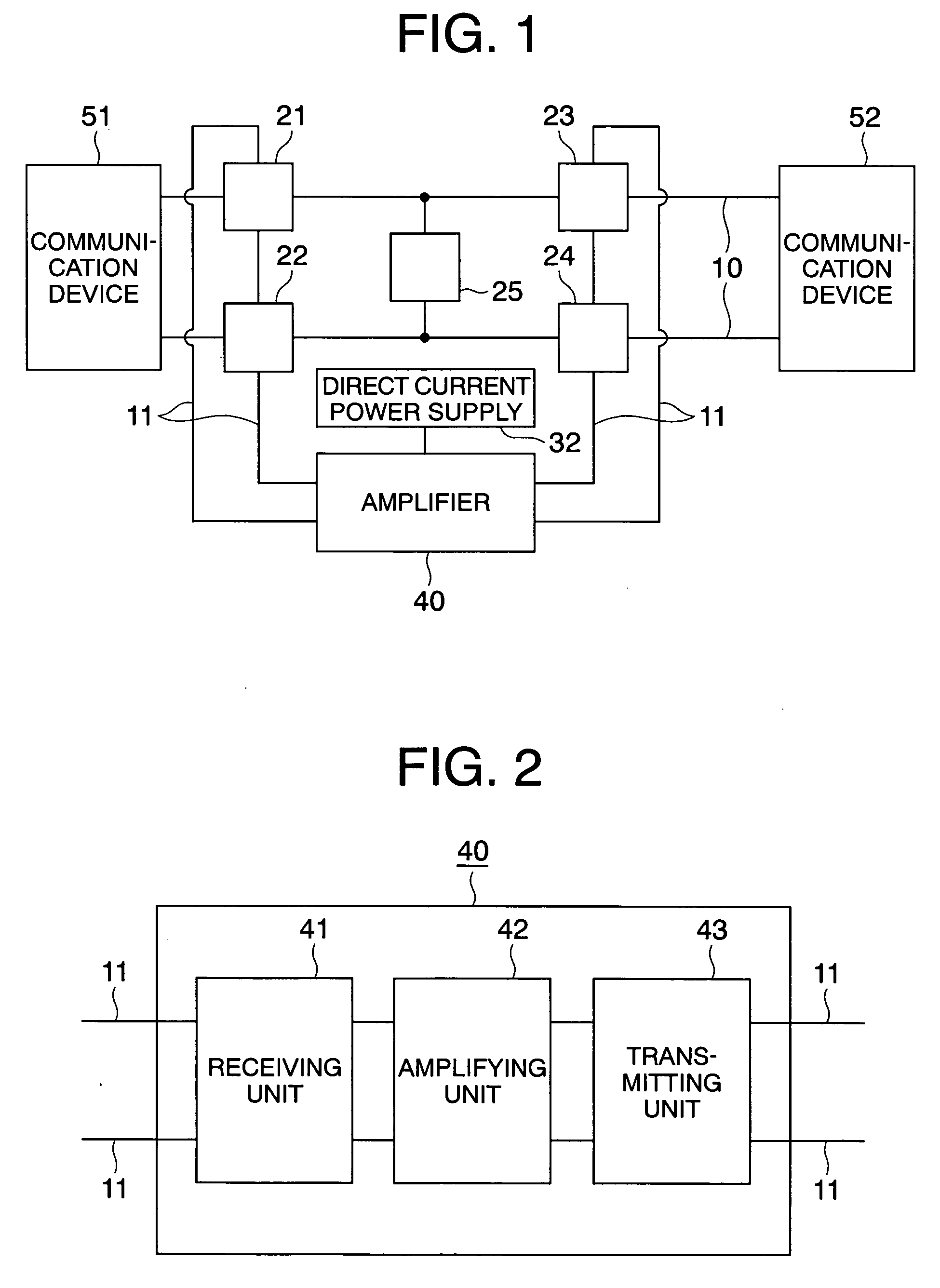
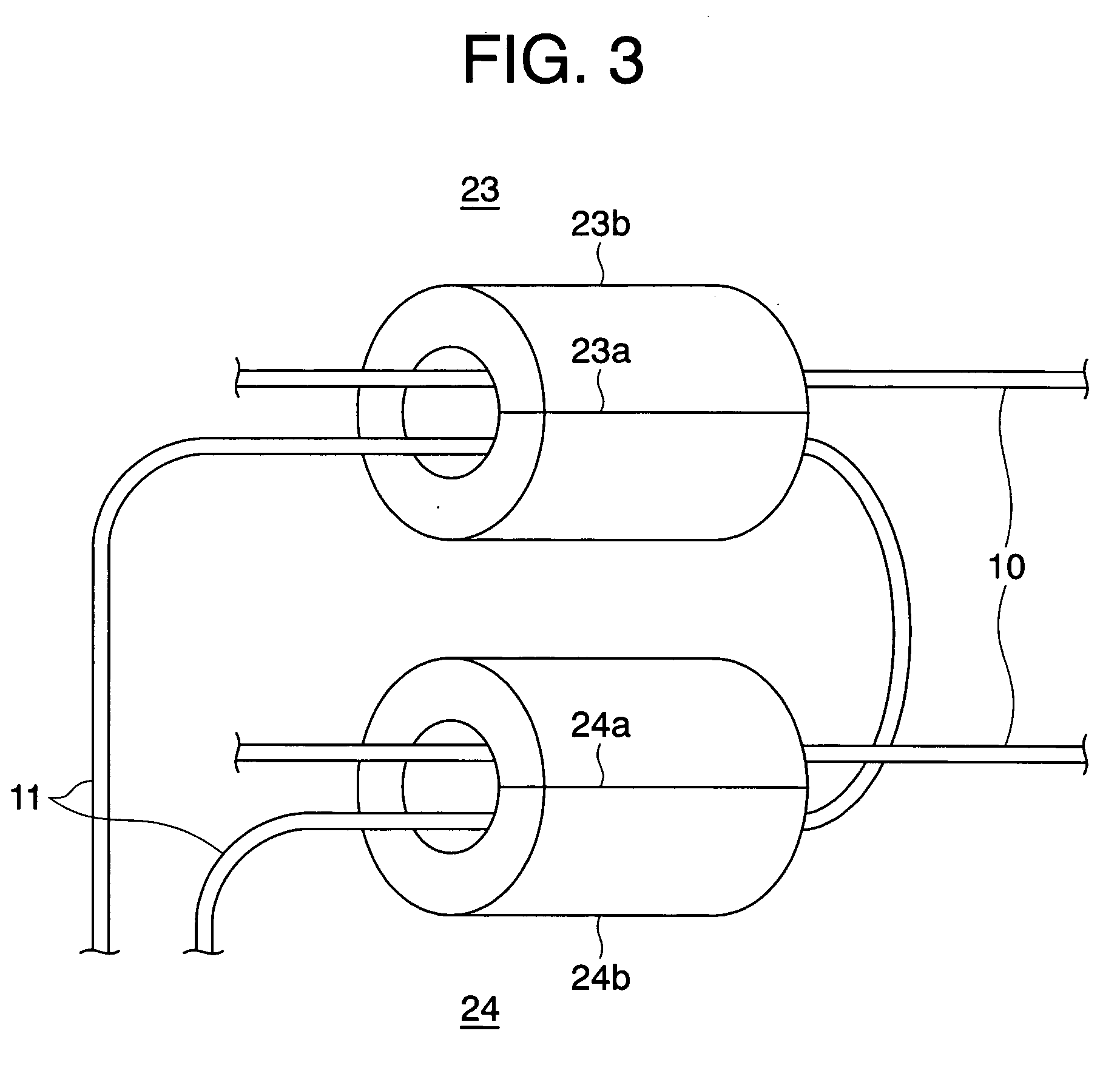
[0017] A description is given with reference to FIGS. 1 to 3 on an over-power line communication system according to a first embodiment of the present invention. FIG. 1 is a block diagram showing a configuration of the over-power line communication system according to the first embodiment of the present invention. FIG. 2 is a block diagram showing a configuration of an amplifier of FIG. 1. FIG. 3 is a perspective view showing how signals couplers of FIG. 1 couple lines. In FIGS. 1 to 3, the same reference symbol denotes the same or corresponding component.

[0018] In FIG. 1, a relay amplifying device of the over-power line communication system according to the first embodiment has four signal couplers 21, 22, 23, and 24, which electromagnetically couple power lines 10 with signal lines 11 between communication devices 51 and 52, a low impedance circuit unit 25, which is a capacitor or the like having an impedance value of a few ohm (Ω) or lower and connected between the two power lin...

second embodiment

[0030] A description is given with reference to FIG. 4 on an over-power line communication system according to a second embodiment of the present invention. FIG. 4 is a block diagram showing a configuration of the over-power line communication system according to the second embodiment of the present invention.

[0031] In FIG. 4, a relay amplifying device of the over-power line communication system according to the second embodiment has four signal couplers 21, 22, 23, and 24, which electromagnetically couple power lines 10 with signal lines 11 between communication devices 51 and 52, and a relay amplifier 100, which amplifies transmission signals.

[0032] The relay amplifier 100 is composed of a power supply circuit 30, which is connected to the power lines 10, and an amplifier 40.

[0033] The power supply circuit 30 is composed of a low impedance circuit unit 25, which is connected between the two power lines 10, and a power supply unit 31, which is also connected between the power li...


PUM


Abstract

An over-power line communication system has a low impedance circuit unit, which is connected between the power lines, first signal couplers, which are set on the first communication device side to the low impedance circuit unit to electromagnetically couple the power lines with one of signal lines, second signal couplers, which are set on the second communication device side to the low impedance circuit unit to electromagnetically couple the power lines with the other of the signal lines, and an amplifier, which receives transmission signals taken out onto one of the signal lines by the first signal couplers, amplifies the received transmission signals, and sends the amplified signals to the other of the signal lines. The transmission signals amplified and then sent to the other of the signal lines are injected to the power lines by the second signal couplers.

Description

BACKGROUND OF THE INVENTION [0001] 1. Field of the Invention [0002] The present invention relates to a communication system for over-power line communications where power lines serve as transmission paths. More specifically, the present invention relates to a relay amplifying device of an over-power line communication system that is installable by inserting elements in parallel to power lines. [0003] 2. Description of Related Art [0004] In relay amplification along a normal communication path, it is easy to separate reception signals from transmission signals, and oscillations caused by transmission signals encroaching on reception signals can be avoided by separating the two from each other. However, in over-power line communication systems which use power lines as transmission paths, it is difficult to separate reception signals from transmission signals physically. Over-power line communication systems therefore prevent the oscillations by inserting elements in series with power ...

Claims


Application Information

Patent Timeline
Patent Type & Authority Applications(United States)
IPC IPC(8): G05F1/00
CPCH02J13/0027H04B3/58Y02E60/7892Y04S40/146H04B2203/5483H02J13/00009Y02E60/00Y04S40/121
Inventor HORI, YASUAKI
Owner MITSUBISHI ELECTRIC CORP
Learn More