
Method and apparatus for distributing multiple signal inputs to multiple integrated circuits

a technology of integrated circuits and signals, applied in the field of multi-tuner receiver systems, can solve the problems of difficult splitting and distributing signals to multiple devices, affecting the power level balance, and reducing the signal to noise ratio (snr) of the signal, so as to reduce the degradation of the signal, simplify the circuit board routing, and reduce the effect of signal degradation

Active Publication Date: 2006-12-07
ENTROPIC COMM INC
View PDF19 Cites 18 Cited by
  • Summary
  • Abstract
  • Description
  • Claims
  • Application Information

AI Technical Summary

Benefits of technology

[0010] An integrated circuit (IC) structure and method of distributing multiple signal inputs to multiple integrated circuits, where each IC receives at least one original signal and outputs a replica of the original signals to other ICs and receives at least one replica signal output by another IC. In one embodiment, the IC can contain one or more television signal tuners on one die and is called an IC tuner. The ICs can convert the single ended format of the received signal to differential for interference rejection. The invention enables an efficient solution for distribution of signals to multiple ICs by eliminating the need for extra components to split and amplify the signals. The invention also minimizes degradation of the signal as it is distributed to multiple devices because no power splitting of the signal occurs. A signal from one source is routed to one destination allowing for simplified circuit board routing and thus impedance levels are maintained and power balance is preserved.

Problems solved by technology

The power splitting and amplification results in a degradation of the signal to noise ratio (SNR) of the signal.
When using a two-layer circuit board, splitting and distributing signals to multiple devices is difficult due to the need for signal crossovers, disruption of the ground plane, and switching between layers.
These routing issues in the circuit board wiring disturb the controlled impedance of the wiring and alter the power level balance across the broadband signal and among the various signals.
A further problem is implementing splitters on a circuit board for signal frequencies below standard satellite intermediate frequencies, which is challenging due to the long wavelengths and large circuit element sizes.

Method used


Image

  • Method and apparatus for distributing multiple signal inputs to multiple integrated circuits
  • Method and apparatus for distributing multiple signal inputs to multiple integrated circuits
  • Method and apparatus for distributing multiple signal inputs to multiple integrated circuits

Examples


Embodiment Construction

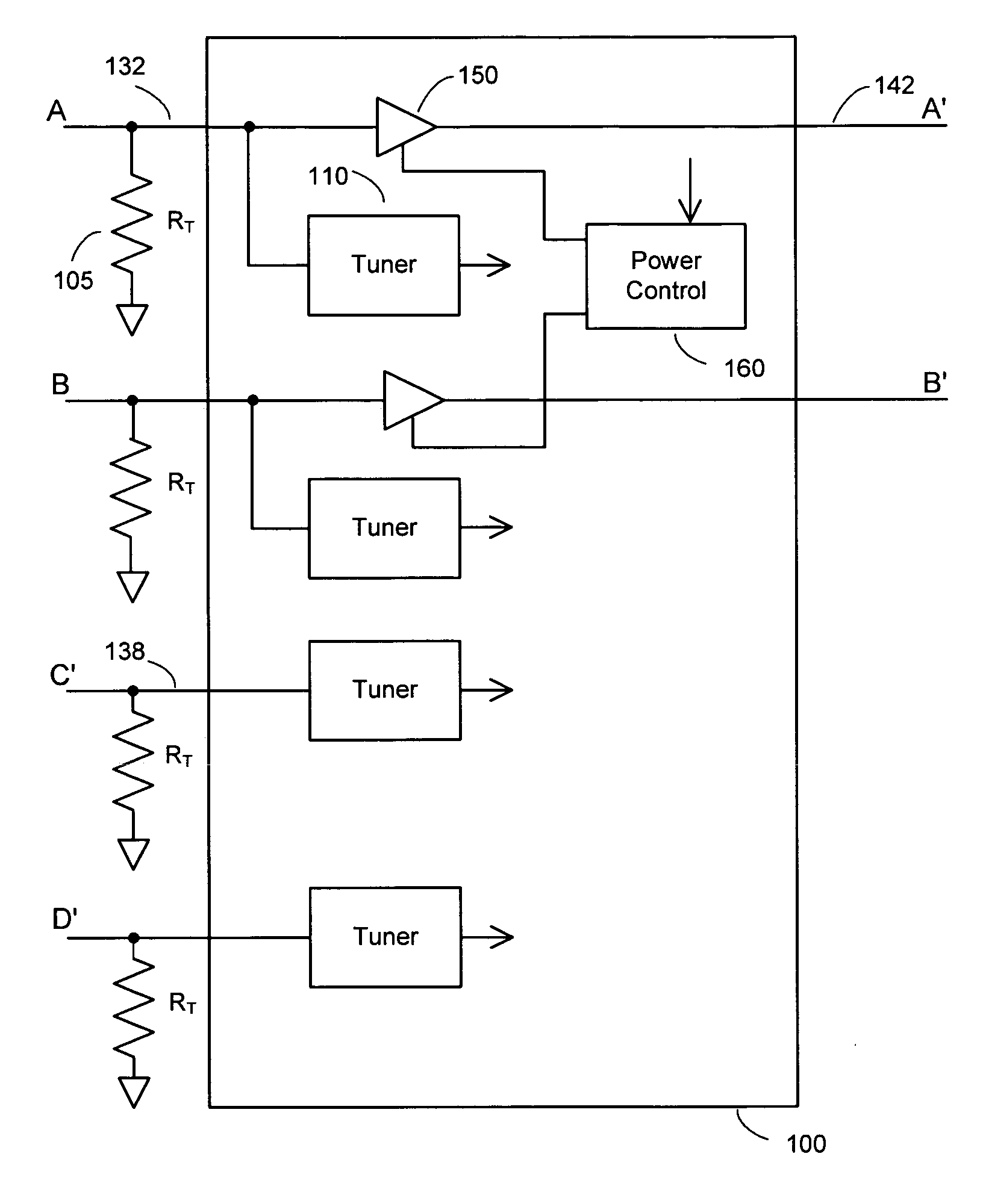
[0024]FIG. 3 shows signal processing inside an integrated circuit tuner 100 according to the present invention. Optional termination resistor 105 matches the transmission line characteristic impedance of input signal 132 and can be external to the IC, as shown, or internal, or omitted in some applications. One tuner 110 is provided for each input signal. A selected number of the input signals 132 are replicated by a buffer amplifier 150 and drive output 142. The amplifier 150 has a power enable input that allows the power to be tuned off by a power control circuit 160, thereby disabling the output signal. Power control 160 can accept a power control signal from an internal programmable register or an input pin to the IC. Other input signals, for example C′138 are received from another IC and are not replicated. In the embodiment shown, one tuner is provided for each input signal.

[0025]FIG. 4 shows another embodiment of the integrated circuit tuner 200 using data selectors 220, also...


PUM


Abstract

An integrated circuit (IC) structure and method of distributing multiple broadband signal inputs to multiple integrated circuits, where each IC receives at least one original signal and outputs a replica of the original signals to other ICs and receives at least one replica signal output by another IC.

Description

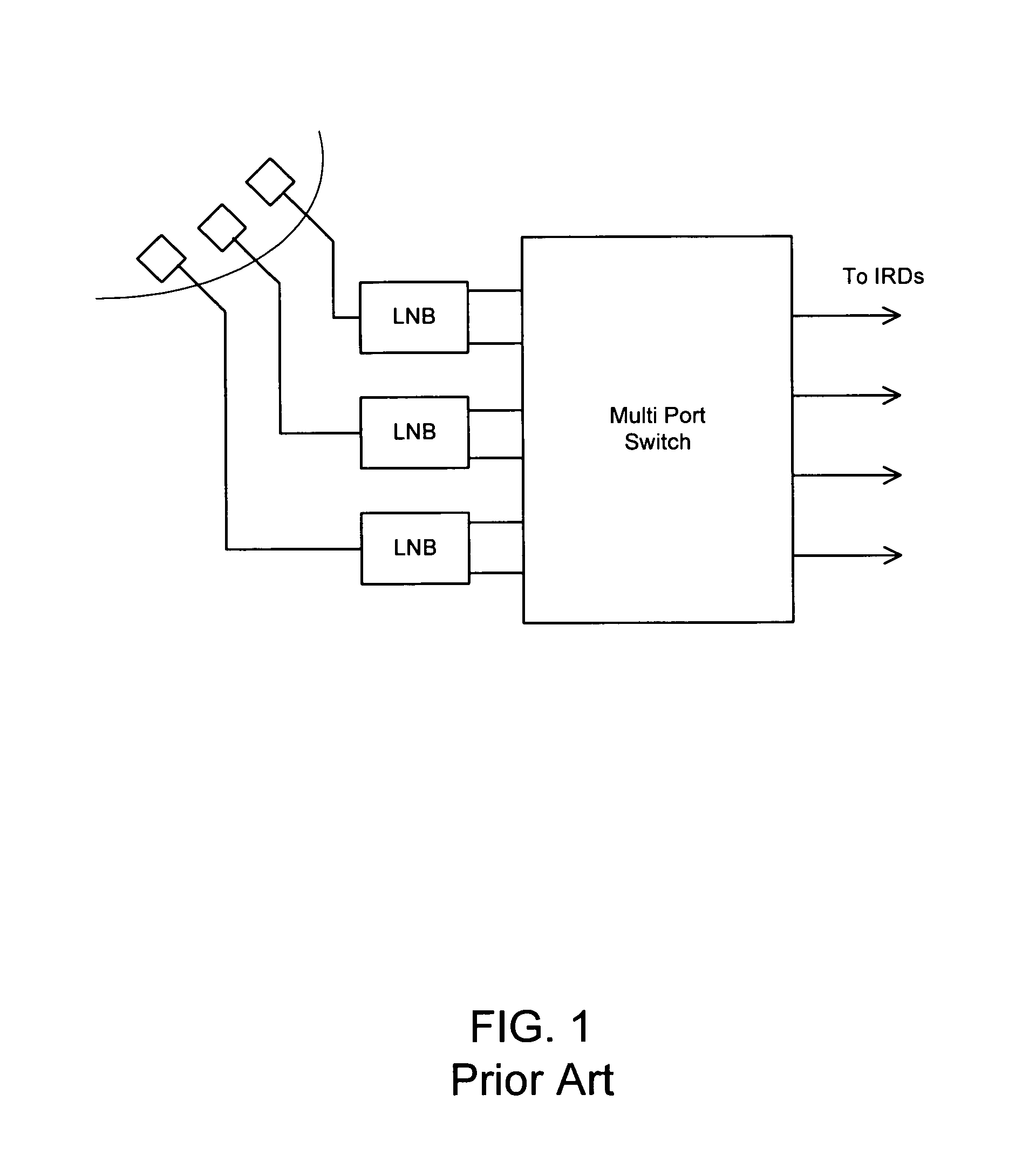
RELATED APPLICATIONS [0001] This application claims the benefit of U.S. Provisional Application No. 60 / 677,745 filed May 4, 2005 entitled “Method and apparatus for distributing multiple signal inputs to multiple integrated circuits” and incorporated herein by reference.BACKGROUND [0002] 1. Field of the Invention [0003] The present invention relates to multiple-tuner receiver systems and specifically to distribution of multiple received signals to multiple tuners. [0004] 2. Prior Art [0005]FIG. 1 shows an application requiring the distribution and processing of multiple signals in a direct broadcast satellite (DBS) receiver system where there are multiple low noise block converters (LNBs) that receive signals from multiple satellite transmitters. Additionally, each satellite signal may have a horizontal and vertical polarized signal that results in two output signals from each LNB. For a three LNB receiver antenna, there could be six independent bands of signals that require distribu...

Claims


Application Information

Patent Timeline
IPC IPC(8): H04N7/20
CPCH03J5/244H04B1/18H04N5/4446H04N21/4263H04N7/104H04N7/20H04N5/50
Inventor GOLDBLATT, JEREMYKITT, JOHNDOHERTY, PETER
Owner ENTROPIC COMM INC
Learn More