
One piece dental implant and use thereof in prostodontic and orthodontic applications

a technology of dental implants and prostheses, applied in the field of dental implants, can solve the problems of inability to integrate into a single device, loose connections between the o-ring abutments and the dental implant bodies, and fixtures that exhibit bacteria and ionic micro-leakage at the joints,

Inactive Publication Date: 2006-12-07
3M IMTEC
View PDF3 Cites 52 Cited by
  • Summary
  • Abstract
  • Description
  • Claims
  • Application Information

AI Technical Summary

Benefits of technology

[0012] Therefore, it was another object of the present invention to provide a means that would allow the practitioner to “switch” from the use of O-ring-shaped inserts to the use of plastic inserts or vice versa without having to remove the keeper cap from the denture or to form a new denture around new keeper caps. SUMARY OF INVENTION

Problems solved by technology

Previously, these have not been integrated into a single device.
A problem with these types of fixtures is that the connections between the O-ring abutments and the dental implant bodies can loosen over time.
Another problem is that these types of fixtures exhibit bacteria and ionic microleakage at the joints.
A third problem is that the standard implant bodies typically are large in diameter, and this causes problems in setting these implant bodies in the bone.
Specifically, surgical intervention is required, which translates to multiple office visits and increased costs, which increases both the physical and financial discomfort to the patient.
Previously, the flexibility to use either the O-ring-shaped insert or the plastic insert has not been enjoyed.
This is undesirable because the O-ring-shaped inserts are conventionally made of rubber, and, thus, are more gentle, and therefore have their greatest usefulness early on in the treatment when the patient's comfort level is low.

Method used


Image

  • One piece dental implant and use thereof in prostodontic and orthodontic applications
  • One piece dental implant and use thereof in prostodontic and orthodontic applications
  • One piece dental implant and use thereof in prostodontic and orthodontic applications

Examples


example

[0080] 1. Jaw Anatomy Evaluation

[0081] The clinician should palpate the labio-lingual or bucco-lingual width dimensions to estimate the optimal direction and angulation for exploratory drill entry through crestal soft tissue then through the cortical bone layer and finally, four to five millimeters into the underlying medullary bone. Bone calipers may also be used to estimate actual bony width, once crestal soft tissue anesthesia is obtained. A point probe may also be used to advantage in estimating soft tissue depth and quality of the underlying bone.

[0082] 2. Drill Specifications

[0083] An appropriate drill may be a tapered 700 XI or 700 XX 1010 or 1012 carbide fissure bur or tapered diamond drill (coarse grain is preferable) used in a friction grip-water-cooled air turbine handpiece. This precision tool is carefully speed controlled by a foot rheostat to provide adequate torque while achieving minimal heat production.

[0084] 3. Drill Technique

[0085] The required drilling is re...


PUM


Abstract

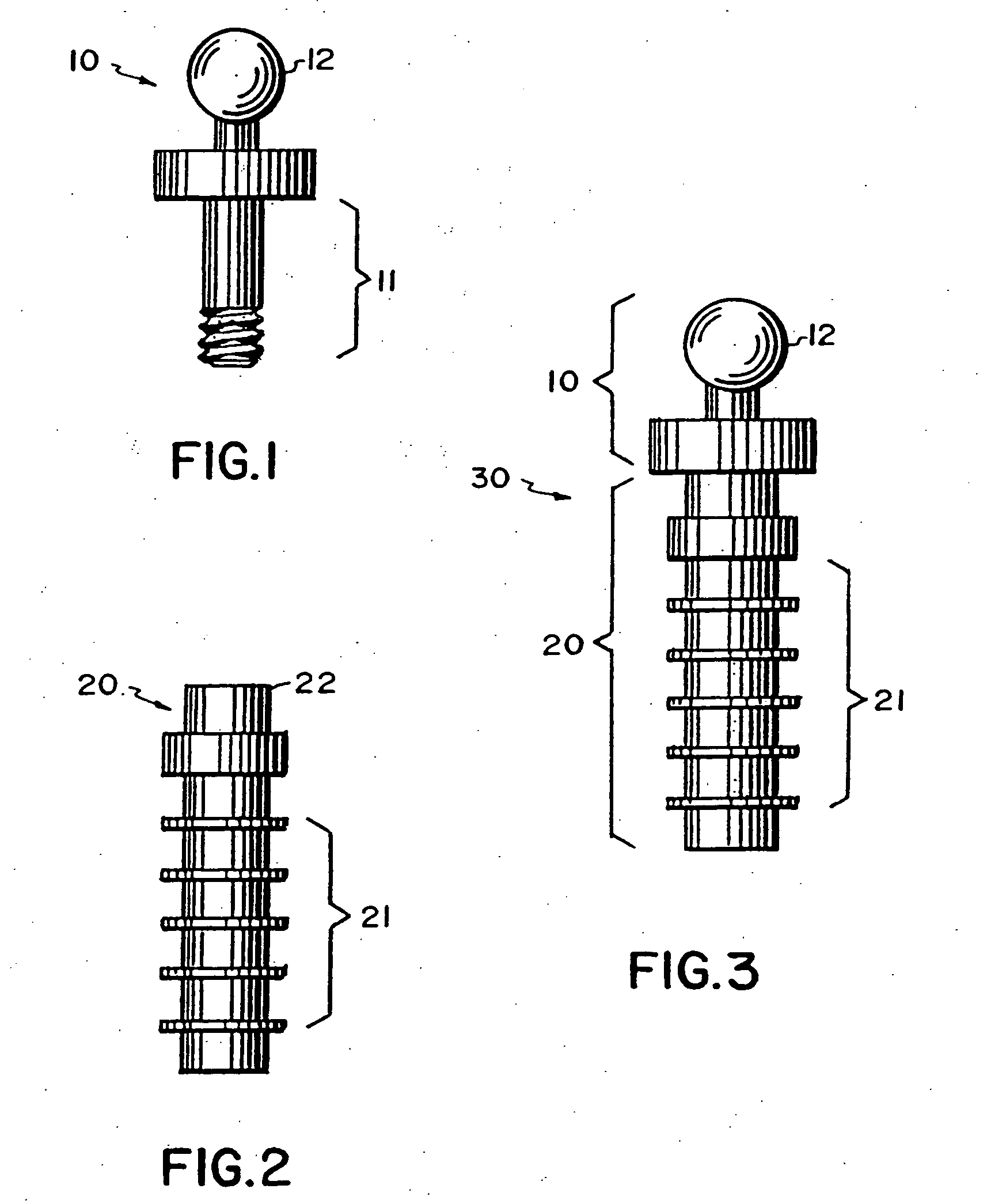
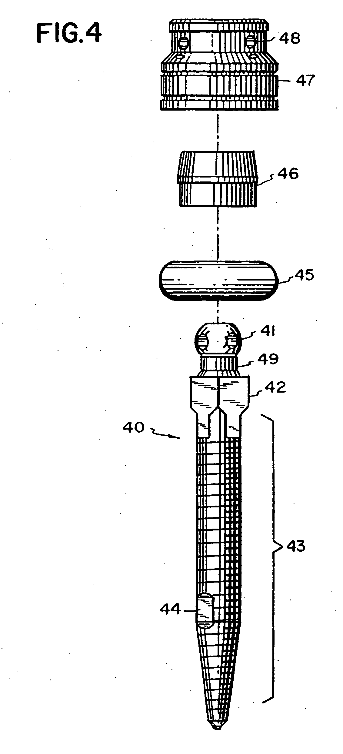
The specification describes one-piece dental implants comprising a threaded shaft, optionally a non-circular abutment and a head having a shape which is capable of accepting a keeper cap or an O-ring, or which is capable of accepting and retaining a dental wire. The implants have dimensions that permit their use in a non-surgical method of insertion into bone, and are useful in both prosthodontic and orthodontic applications. It is emphasized that this abstracts is provided to comply with the rules requiring an abstract which will allow a searcher or other reader to quickly ascertain the subject matter of the technical disclosure. It is submitted with the understanding that it will not be used to interpret or limit the scope or meaning of the claims.

Description

CROSS-REFERENCE TO RELATED APPLICATIONS [0001] This application is a continuation-in-part of U.S. Ser. No. 60 / 532,385, filed on Dec. 26, 2003, and a continuation-in-part of U.S. Ser. No. 60 / 464,958, filed on Apr. 23, 2003; and a continuation-in-part of U.S. Ser. No. 10 / 031,256, filed on Oct. 23, 2001, which is, in turn, a 371 of PCT / US00 / 10827 filed on Apr. 21, 2000, which claims priority of U.S. Ser. No. 60 / 130,864, filed on Apr. 23, 1999. The disclosures of each of these related applications (hereinafter “the related applications”) are fully incorporated herein by reference.BACKGROUND OF THE INVENTION [0002] 1. Field of the Invention [0003] The present invention relates to an improved dental implant, to an improved keeper cap, and to the use of the improved implant and keeper cap for fixed or removable prosthetic applications. [0004] 2. Description of Related Art [0005] The use of combinations of O-ring abutments and standard dental implants is well known in the art. Previously, t...

Claims


Application Information

Patent Timeline
IPC IPC(8): A61C8/00
CPCA61C8/0048A61C13/2656A61C8/0096A61C8/0075
Inventor BULARD, RONALD A.HARDWIN, STEPHEN J.
Owner 3M IMTEC
Learn More