
Volumetric three-dimentional display panel and system using multi-layered organic light emitting devices

a three-dimensional display panel and multi-layered organic technology, applied in static indicating devices, instruments, optical elements, etc., can solve the problems of limited parallax range and viewing angle obtained by lenses, glasses-based and glass-less stereoscopic display techniques have limitations, and achieve simple schemes. the effect of low cos

Active Publication Date: 2006-12-07
SAMSUNG ELECTRONICS CO LTD
View PDF24 Cites 35 Cited by
  • Summary
  • Abstract
  • Description
  • Claims
  • Application Information

AI Technical Summary

Benefits of technology

The present invention provides a cost-effective and simple way to create a complete 3D image using a volumetric 3D display panel. This panel is made up of multiple transparent flat display panels that are stacked and each shows a different 2D image to create a single 3D image. The panels are made up of organic light-emitting devices with a thickness of 2 mm or less. The system includes a controller that distributes multiple 2D images with depth information to the panels, allowing for a more immersive viewing experience. The controller can also interact with the input 3D image through rotation, translation, or zooming in / out.

Problems solved by technology

Furthermore, both the glasses-based and glass-less stereoscopic display techniques have a limit in that only a depth of an object is reproduced; that is, viewers cannot enjoy all of the images of an object as viewed in various directions.
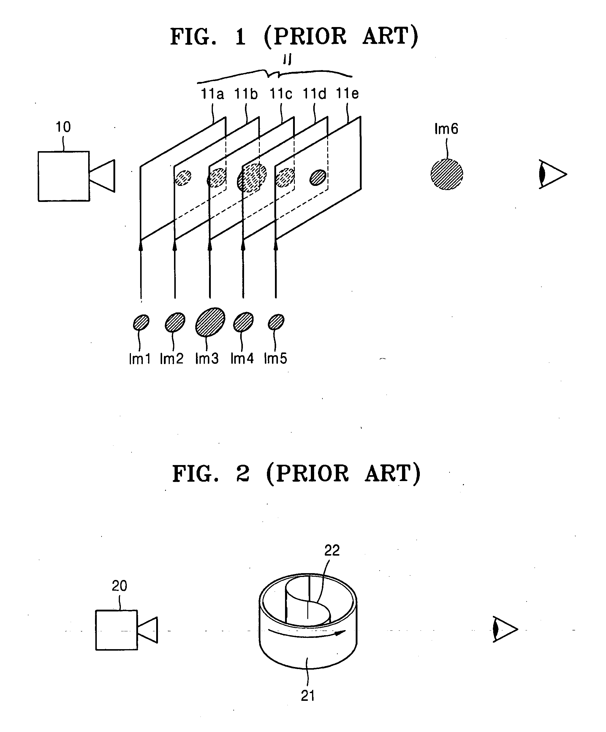
However, the integral photography has a disadvantage in that a parallax range and a viewing angle obtained by a lens are restricted.
The holography has disadvantages in that a coherent light source, such as a laser, is required and that recording and reproducing a large object located at a far distance is difficult.
However, in this conventional volumetric 3D display device, a motor (not shown) for rotating the screen 22 may generate noise, and forming a large volumetric 3D display system using a large screen is difficult due to friction between the screen 22 and the frame 21 and to air resistance.
Furthermore, a volumetric 3D display system using this conventional volumetric 3D display device is prone to break due to the friction and air resistance, so that the lifespan of the system decreases.

Method used


Image

  • Volumetric three-dimentional display panel and system using multi-layered organic light emitting devices
  • Volumetric three-dimentional display panel and system using multi-layered organic light emitting devices
  • Volumetric three-dimentional display panel and system using multi-layered organic light emitting devices

Examples


Embodiment Construction

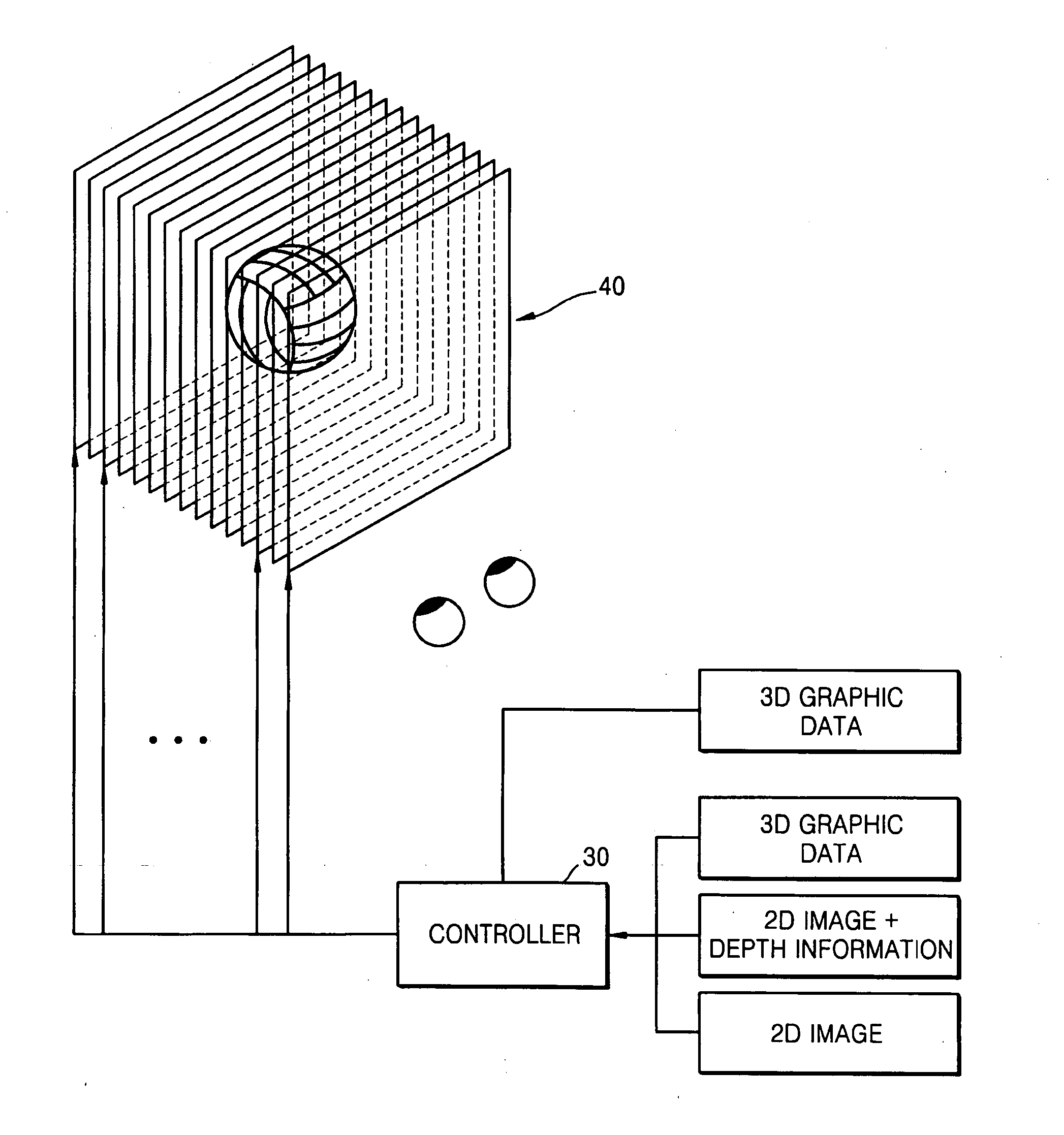
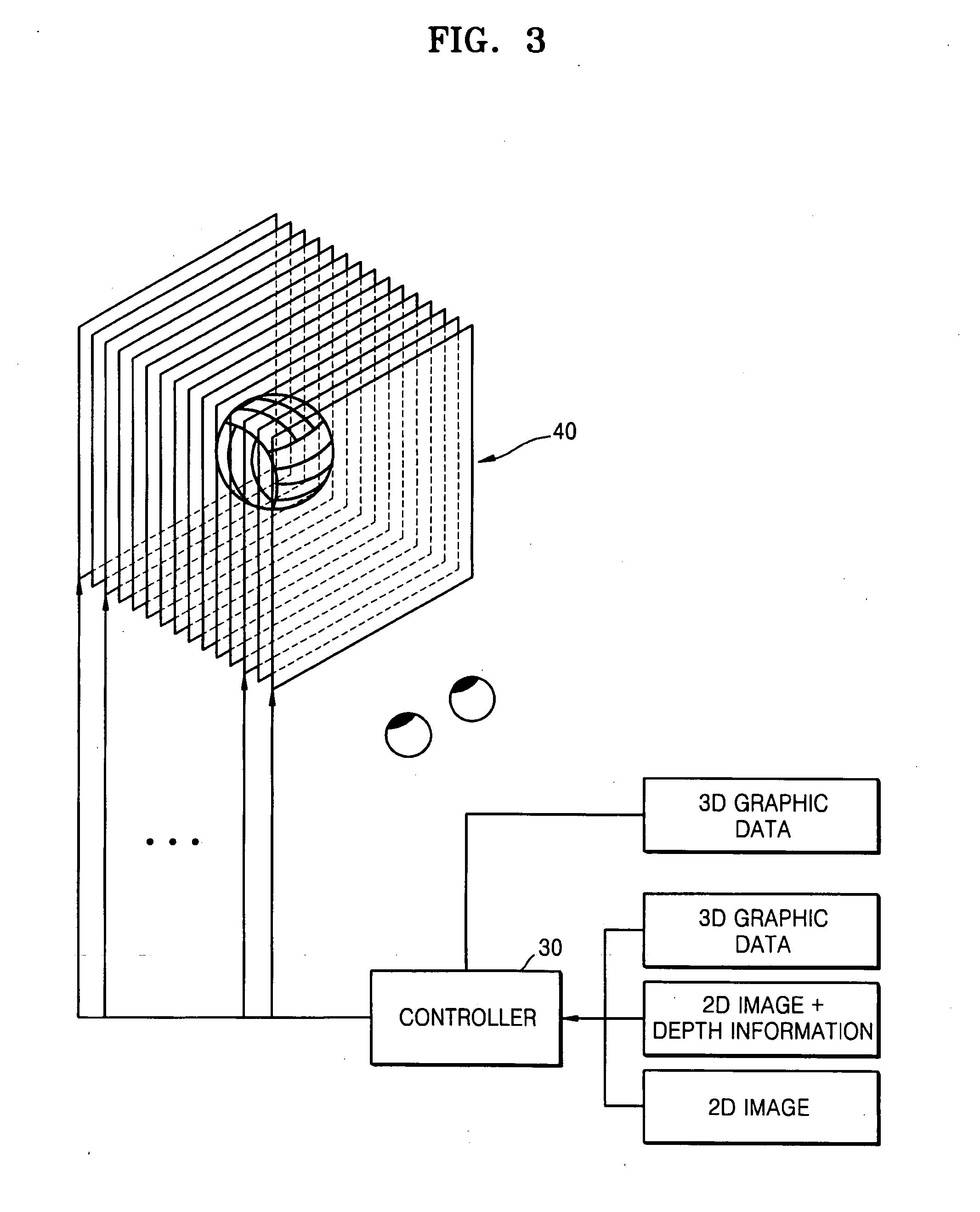
[0028]FIG. 3 schematically illustrates a volumetric 3D display system according to an exemplary embodiment of the present invention. As shown in FIG. 3, the volumetric 3D display system includes a volumetric 3D display panel 40 and a controller 30. The volumetric 3D display panel 40 is a stack of a plurality of transparent flat display panels. The controller 30 distributes a plurality of 2D images having depth information to the plurality of transparent flat display panels according to the depth information of the 2D images and displays the 2D images on the transparent flat display panels. The volumetric 3D display panel 40 is formed by stacking a plurality of thin, transparent flat display panels.

[0029] In the volumetric 3D display system having this structure, each of the transparent flat display panels displays a 2D image. The 2D images displayed on the transparent flat display panels are images into which a 3D image is divided according to depth information. The controller 30 d...


PUM


Abstract

A volumetric three-dimensional display panel and a volumetric three-dimensional display system employing the volumetric three-dimensional display panel are provided, wherein the volumetric three-dimensional display panel is formed by stacking a plurality of transparent flat display panels, such as, organic light-emitting devices. In the volumetric three-dimensional display panel, two-dimensional images are displayed on the transparent three-dimensional display panels, respectively, to form a single three-dimensional image.

Description

CROSS-REFERENCE TO RELATED PATENT APPLICATIONS [0001] This application claims the benefit of priority from Korean Patent Application No. 10-2005-0046733, filed on Jun. 1, 2005, in the Korean Intellectual Property Office, the disclosure of which is incorporated herein in its entirety by reference. BACKGROUND OF THE INVENTION [0002] 1. Field of the Invention [0003] Apparatuses and systems consistent with the present invention relate to a volumetric three-dimensional (3D) display panel and a volumetric 3D display system using the volumetric 3D display panel, and more particularly, to a volumetric 3D display panel formed by stacking a plurality of transparent display panels like organic light-emitting devices and to a volumetric 3D display system using the volumetric 3D display panel. [0004] 2. Description of the Related Art [0005] A 3D image is formed according to the principle of a stereoscopic vision through two eyes of a human being. A binocular parallax, which is generated due to s...

Claims


Application Information

Patent Timeline
Patent Type & Authority Applications(United States)
IPC IPC(8): G09G5/00H04N13/363H04N13/395
CPCG02B27/2278G09G3/003H04N13/0495H01L25/046G09G3/3208H01L2924/0002H04N13/395G02B30/52H04N13/363H10K19/901H01L2924/00H05B33/12
Inventor KOO, JAE-PHILKIM, DAE-SIKKIM, SU-GUN
Owner SAMSUNG ELECTRONICS CO LTD
Learn More