
Differential measurement probe having retractable double cushioned variable spacing probing tips with EOS/ESD protection capabilities

a variable spacing, probing tip technology, applied in the field of signal acquisition probes, can solve the problems of damage to one or both rf pins, variable spacing differential probes that do not have the capability to protect the sampling head, and damage to the sampling circuit in the sampling head

Active Publication Date: 2006-11-30
TEKTRONIX INC
View PDF5 Cites 14 Cited by
  • Summary
  • Abstract
  • Description
  • Claims
  • Application Information

AI Technical Summary

Benefits of technology

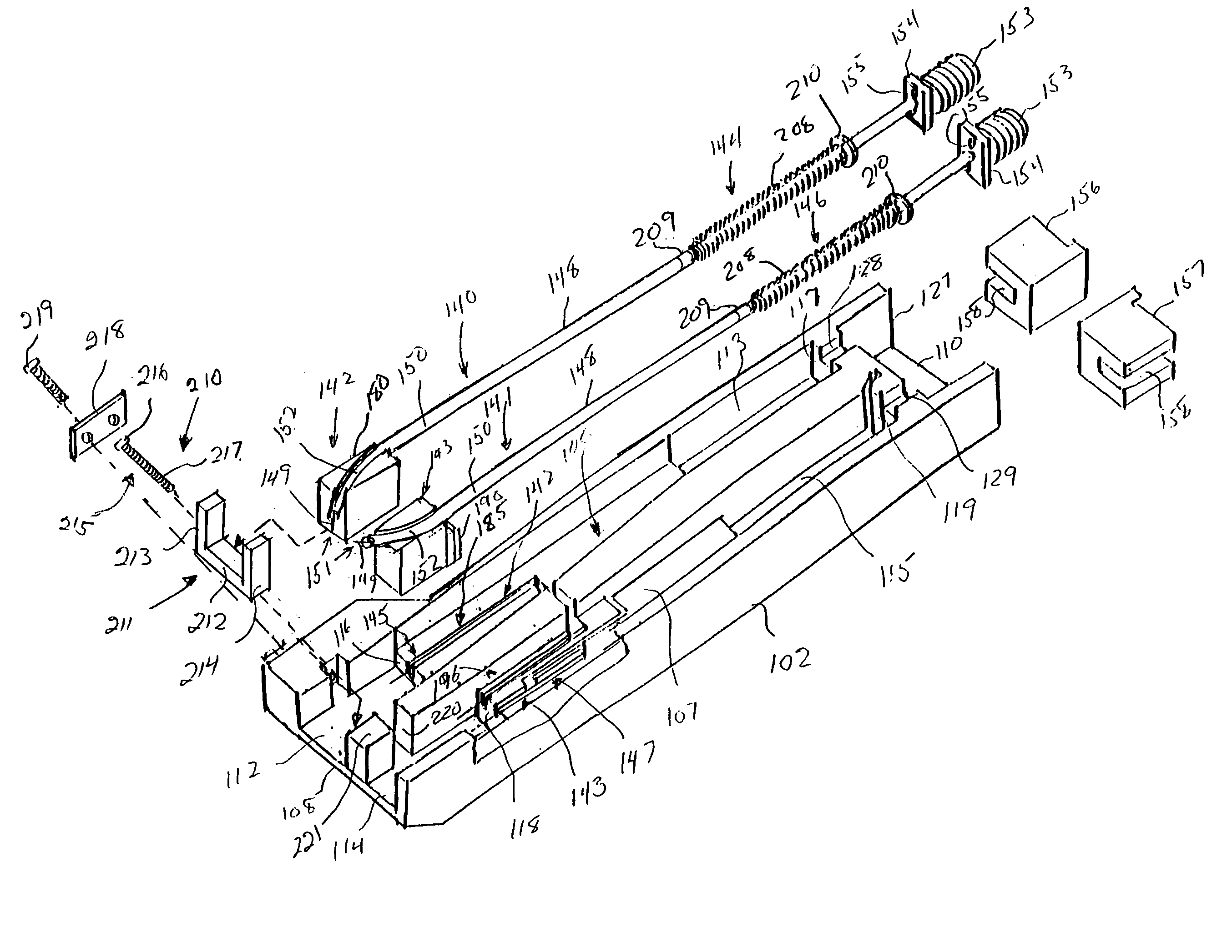
[0020] In the preferred embodiment, each of the first and second coaxial probe assemblies further have an attachment plate disposed on the semi-rigid coaxial cable adjacent to the threaded connector. Each attachment plate is secured to an anti-rotation block which is positioned within the housing. A bracket having a top plate and depending sidewalls is secured to one of the attachment plates. At least a first electrical connector receptacle is mounted on the bracket and is electrically coupled one of the first and second pressure sensors by and electrical conductor.
[0021] A differential measurement probe is preferably coupled via first and second coaxial cables to at least a first electrical over stress and electrostatic discharge protection control module. The differential measurement probe passes the activation signal to the electrical over stress and electrostatic discharge protection control module for electrically coupling the probing tips of the differential measurement probe to input circuitry of the measurement test instrument. One of the second electrically conductive contacts of the first and second pressure sensors is coupled to the electrical over stress and electrostatic discharge protection control module via the electrical conductor. The probing tips of the first and second coaxial probe assemblies are coupled to electrical ground via the electrical over stress and electrostatic discharge protection control module prior to the first electrically conductive contacts of the first and second pressure sensors engaging the second electrically conductive contacts of the first and second pressure sensors. The probing tips of the first and second coaxial probe assemblies are coupled to the input circuitry of the measurement test instrument when the electrical over stress and electrostatic discharge protection control module receives the activation signal passed by the first and second pressure sensors in response to the first electrically conductive contacts of the first and second pressure sensors engaging the second electrically conductive contacts of the first and second pressure sensors.
[0022] The electrical conductor coupling one of the second electrically conductive contacts of the first and second pressure sensors to the electrical over stress and electrostatic discharge protection control module preferably has first and second insulated wire segments. The first insulated wire segment electrically couples one of the second electrically conductive contacts of the first and second pressure sensors to an electrical contact of the electrical connector receptacle mounted on the differential measurement probe. The second insulated w

Problems solved by technology

While the above described variable spacing TDR probe allows movement of the RF tips and the ground pogo pins, the design of the probe has drawbacks.
If this axial force is excessive, then damage can occur to one or both of the RF pins.
Further, this variable spacing differential probe does not have the capability to protect the sampling head from electrostatic voltages that may be present on the device under test.
This will result in damage to the sampling circuit in the sampling head.
This introduces unique problems.
The excess forces on the pressure sensor and the coaxial probe assembly may result in damage to the pressure sensor or the coaxial probe assembly.

Method used


Image

  • Differential measurement probe having retractable double cushioned variable spacing probing tips with EOS/ESD protection capabilities
  • Differential measurement probe having retractable double cushioned variable spacing probing tips with EOS/ESD protection capabilities
  • Differential measurement probe having retractable double cushioned variable spacing probing tips with EOS/ESD protection capabilities

Examples


Embodiment Construction

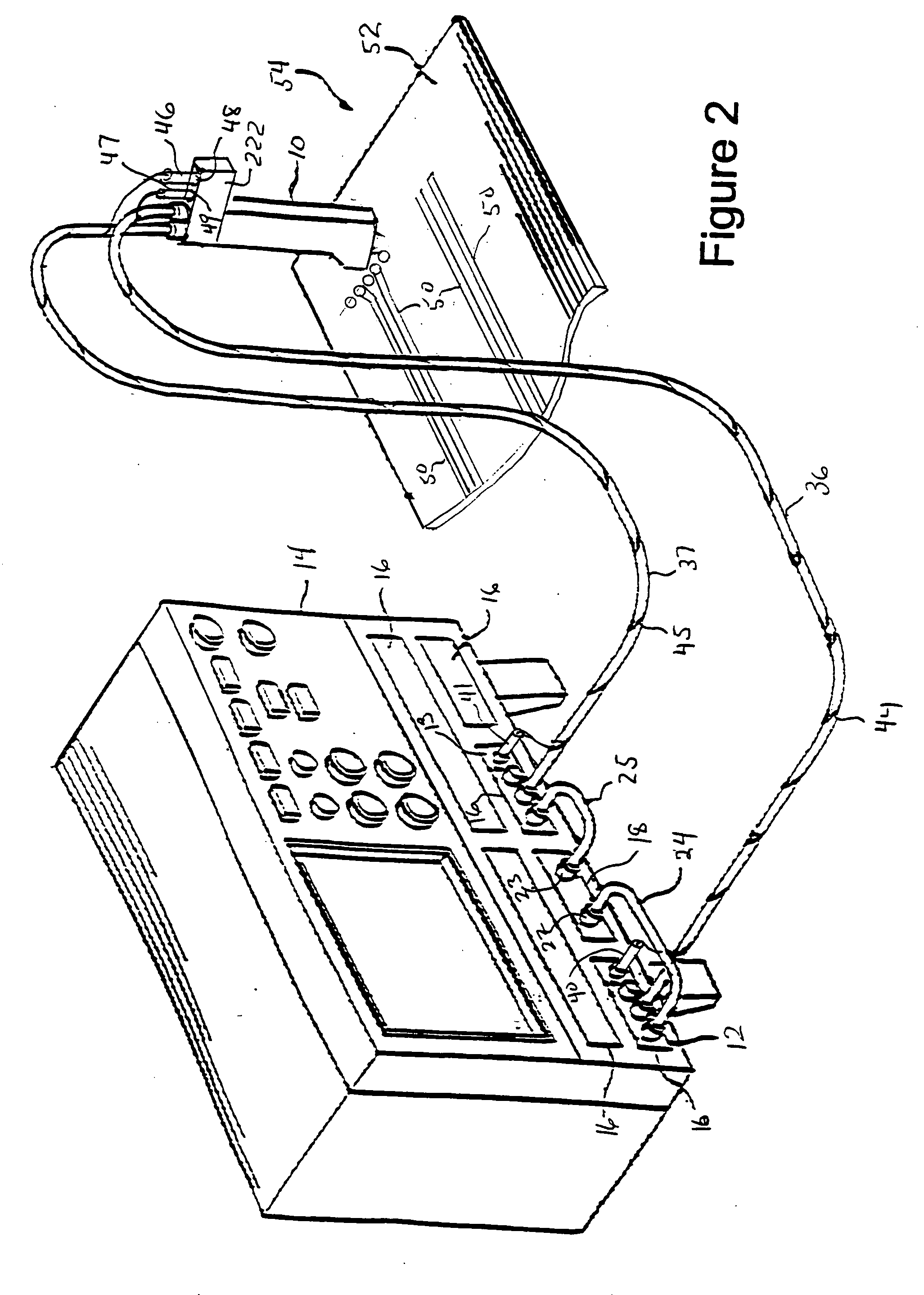
[0042] Referring to FIG. 2, there is shown a representative view of a differential measurement probe 10 having retractable double cushioned variable spacing probing tips for passing an activation signal to first and second electrical over stress (EOS) and electrostatic discharge (ESD) protection control modules 12, 13. The control modules 12, 13 are disposed in a measurement test instrument 14, preferably a sampling oscilloscope, such as the TDS82000 Digital Sampling Oscilloscope, manufactured and sold by Tektronix, Inc., Beaverton, Oreg. The digital sampling oscilloscope 14 has a modular architecture that includes multiple bays 16 for receiving various types of optical and electrical plug-in modules 18. The bays 16 provide power, control signals and signal output for the modules. One such module is the 80E04 Dual Channel TDR Sampling Head that is usable for making TDR measurements. The sampling head 18 has input terminals 22, 23 coupled to first and second channel sampling diodes w...


PUM


Abstract

A differential measurement probe has spring loaded, double cushioned probe assemblies and a pressure sensors disposed in a housing. The pressure sensors forms an electrical switch having an electrical AND function for passing an activation signal to a EOS / ESD protection control module in response to axial movement of the housing relative to the probe assemblies. First compressive elements produces first pre-loaded compressive forces and increasing compressive forces on the probe assemblies and second compressive elements produces second pre-loaded compressive forces and increasing compressive forces on the probe assemblies subsequent to the first increasing compressive forces on the probe assemblies. An adjustment member allows variable spacing of the differential probing tips.

Description

BACKGROUND OF THE INVENTION [0001] The present invention relates generally to signal acquisition probes and more particularly to a differential measurement probe having retractable double cushioned variable spacing probing tips with electrical over stress (EOS) and electrostatic discharge (ESD) protection capabilities. [0002] Differential time domain reflectometry (TDR) probes are used to launch step pulses onto devices under test and receive reflected return pulses from the device. The return pulses are coupled to a sampling head which generates discrete samples of the return signal. Due to the variability of the spacing of test points on the device under test, it is desirable to provide a differential TDR probe with variable spacing probing tips. One such differential TDR probe is the A0134332 Differential TDR probe, manufactured and sold by Inter-Continental Microwave, Santa Clara, Calif. The variable spacing differential TDR probe has individual TDR probes that are mounted to a ...

Claims


Application Information

Patent Timeline
IPC IPC(8): G01R31/02
CPCG01R1/06788G01R1/36G01R1/06794
Inventor YANG, KEI-WEAN C.
Owner TEKTRONIX INC
Learn More