
Pulse width modulation (PWM) rectifier with variable switching frequency

a pwm rectifier and variable switching technology, applied in the direction of motor/generator/converter stopper, dynamo-electric converter control, instruments, etc., can solve the problems of reducing the efficiency of pwm rectifiers, reducing the cost of pwm rectifiers, and avoiding the use of pwm rectifiers in medium-performance applications. , to achieve the effect of reducing the rating requirements, reducing the cost, and reducing the curren

Inactive Publication Date: 2006-11-30
ROCKWELL AUTOMATION TECH
View PDF83 Cites 27 Cited by
  • Summary
  • Abstract
  • Description
  • Claims
  • Application Information

AI Technical Summary

Benefits of technology

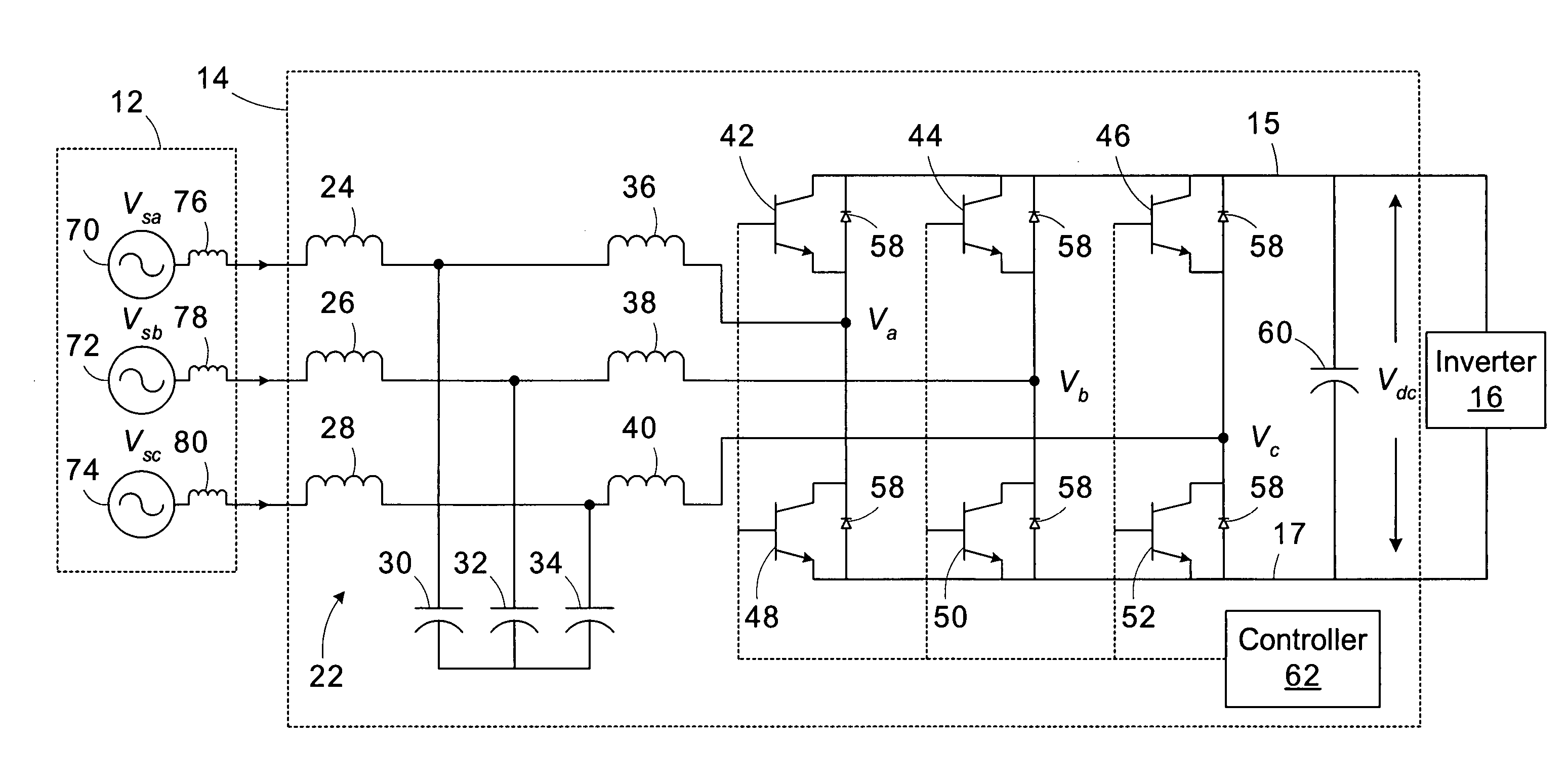
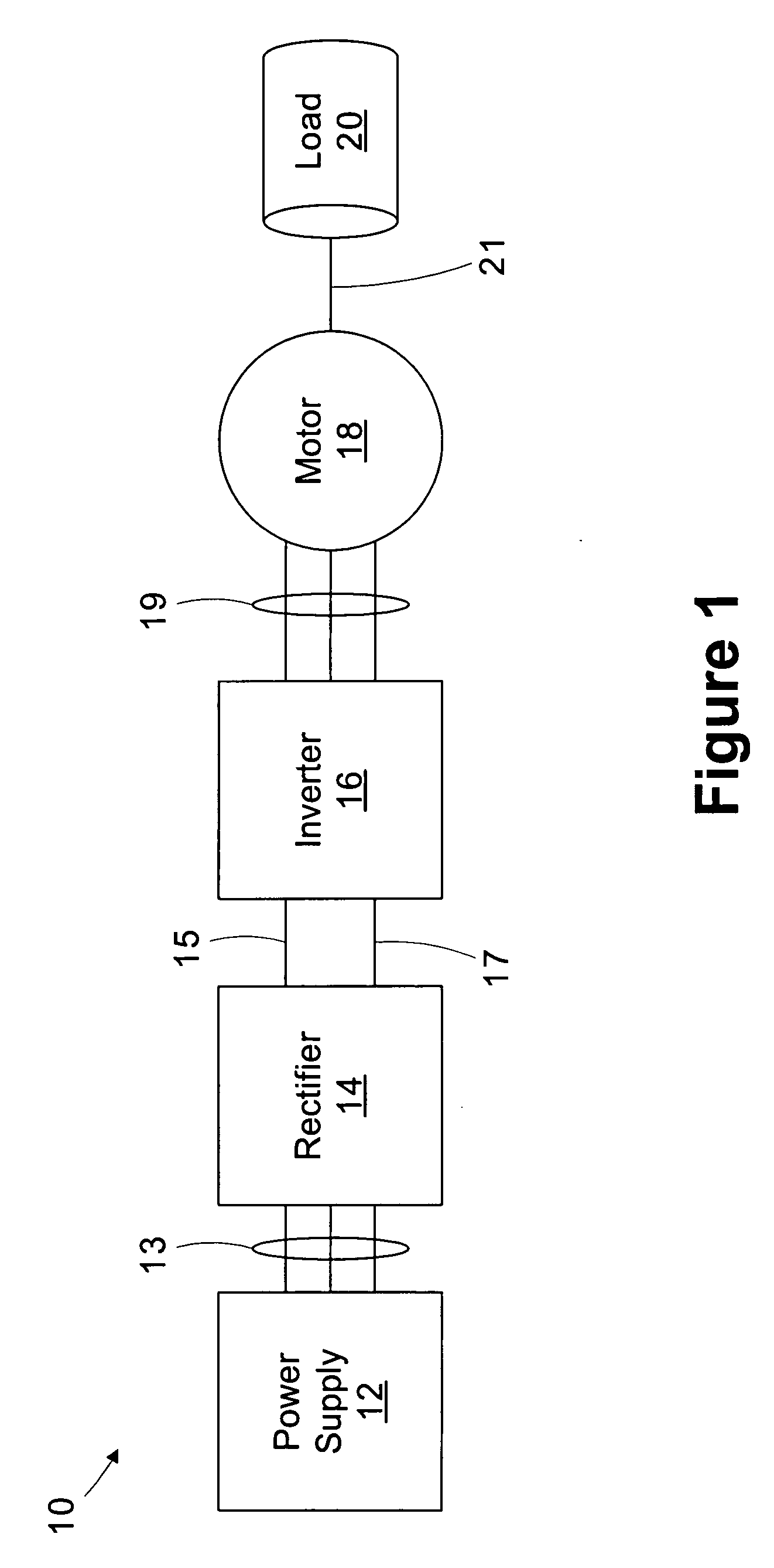
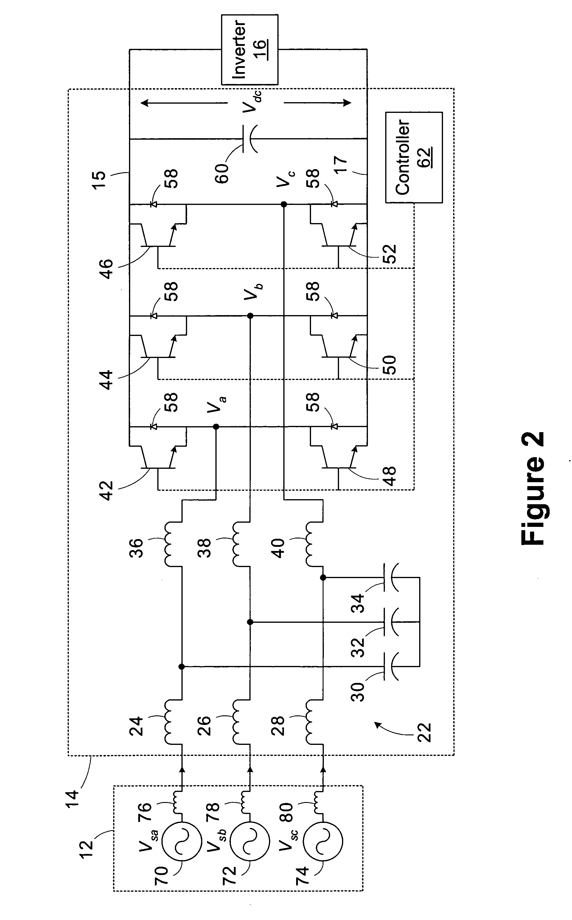
[0011] The present inventors have recognized that main inductor ripple current in a PWM rectifier varies depending on the value of the reference voltage for each phase. The ripple current reaches its maximum value when the reference voltage for the particular phase reaches zero, while the ripple current lessens when the reference voltage reaches its maximum value. By varying the switching frequency of the rectifier depending on the value of the reference voltage, the ripple current and switching losses may be reduced. This performance increase lessens the rating requirements of the inductors and transistor switching devices employed in the rectifier, thereby reducing its cost and expanding its range of applications. The variable frequency pulse width modulation technique is may be used in other applications in addition to rectifier applications.

Problems solved by technology

Diode rectifiers typically encounter difficulty in attempting to met the harmonic distortion constraints.
Typical PWM rectifiers are better able to meet the harmonic distortion requirements, but are more costly than conventional diode rectifiers.
This cost differential has typically precluded the use of PWM rectifiers in medium performance applications.
Significant ripple current results in a higher required rating for the main inductors, thereby increasing their cost.
However, both techniques show significant ripple current, necessitating a larger, more expensive main inductor.

Method used


Image

  • Pulse width modulation (PWM) rectifier with variable switching frequency
  • Pulse width modulation (PWM) rectifier with variable switching frequency
  • Pulse width modulation (PWM) rectifier with variable switching frequency

Examples


Embodiment Construction

[0024] One or more specific embodiments of the present invention will be described below. It is specifically intended that the present invention not be limited to the embodiments and illustrations contained herein, but include modified forms of those embodiments including portions of the embodiments and combinations of elements of different embodiments as come within the scope of the following claims. It should be appreciated that in the development of any such actual implementation, as in any engineering or design project, numerous implementation-specific decisions must be made to achieve the developers' specific goals, such as compliance with system-related and business related constraints, which may vary from one implementation to another. Moreover, it should be appreciated that such a development effort might be complex and time consuming, but would nevertheless be a routine undertaking of design, fabrication, and manufacture for those of ordinary skill having the benefit of thi...


PUM


Abstract

A method for controlling a device including a plurality of switching devices operated in accordance with a pulse width modulation technique includes receiving a reference voltage signal associated with a first pair of the switching devices. A switching signal is generated. The first pair of switching devices are controlled based on the reference voltage signal and the switching signal in accordance with the pulse width modulation technique. A frequency of the switching signal is varied based on the value of the reference voltage signal.

Description

CROSS-REFERENCE TO RELATED APPLICATIONS [0001] Not applicable. STATEMENT REGARDING FEDERALLY SPONSORED RESEARCH OR DEVELOPMENT [0002] Not applicable BACKGROUND OF THE INVENTION [0003] The present invention relates generally to power conversion and conditioning and, more particularly, to a PWM rectifier with a variable switching frequency. [0004] This section of this document is intended to introduce various aspects of art that may be related to various aspects of the present invention described and / or claimed below. This section provides background information to facilitate a better understanding of the various aspects of the present invention. It should be understood that the statements in this section of this document are to be read in this light, and not as admissions of prior art. [0005] Power plants are linked to power consuming facilities (e.g., buildings, factories, etc.) via utility grids designed so as to be extremely efficient in delivering massive amounts of power. To fac...

Claims


Application Information

Patent Timeline
Patent Type & Authority Applications(United States)
IPC IPC(8): H02P7/36
CPCH02M7/219
Inventor WEI, LIXIANGLUKASZEWSKI, RICHARD A.
Owner ROCKWELL AUTOMATION TECH
Learn More