
Work-table

a worktable and work surface technology, applied in the field of worktables, can solve the problems of inability to detect the hit obstruction on the basis of a motor load monitoring, endanger the obstruction, etc., and achieve the effect of improving the monitoring of the load of the worktable and high precision

Inactive Publication Date: 2006-11-30
LOGICDATA ELECTRONICS & SOFTWARE
View PDF11 Cites 42 Cited by
  • Summary
  • Abstract
  • Description
  • Claims
  • Application Information

AI Technical Summary

Benefits of technology

[0005] Since as a result of this measure the load of at least one load-dissipating part of the frame is detected directly by way of a wire resistance strain gauge or a force transducer, the respective table loads can be monitored with a comparatively high precision, irrespective of the respective frictional conditions in the guide area of the adjusting part of the frame or in the region of the actuating drive in order to intervene in the motor control in the case of a respective change of the load of the load-dissipating part and to enable the cut-off of the electric motor optionally after a reversal of the direction of rotation. In order to improve the monitoring of the load of the work-table or changes in load, two or more load-dissipating parts of the frame can be provided with measuring tape or be supported on force transducers, because the load conditio...

Problems solved by technology

There is a likelihood in work-tables with a frame which can be adjusted in its height by at least one actuating drive driven by a motor that during the adjustment of the frame an obstruction in the path of the adjustment is hit, leading to an endangerment of the obstruction, as also the work-table or items situated on the work-table when the electromotor is not switched off.
Since the motor load depends, among other things, on the frictional conditions in the region of the actuating drive and the guidance of the adjusting part of the table frame and these frictional conditions can change, a sensitive detection of the hit obstructions on the basis of a monitoring of the motor load is not possible.

Method used


Image

  • Work-table
  • Work-table
  • Work-table

Examples


Embodiment Construction

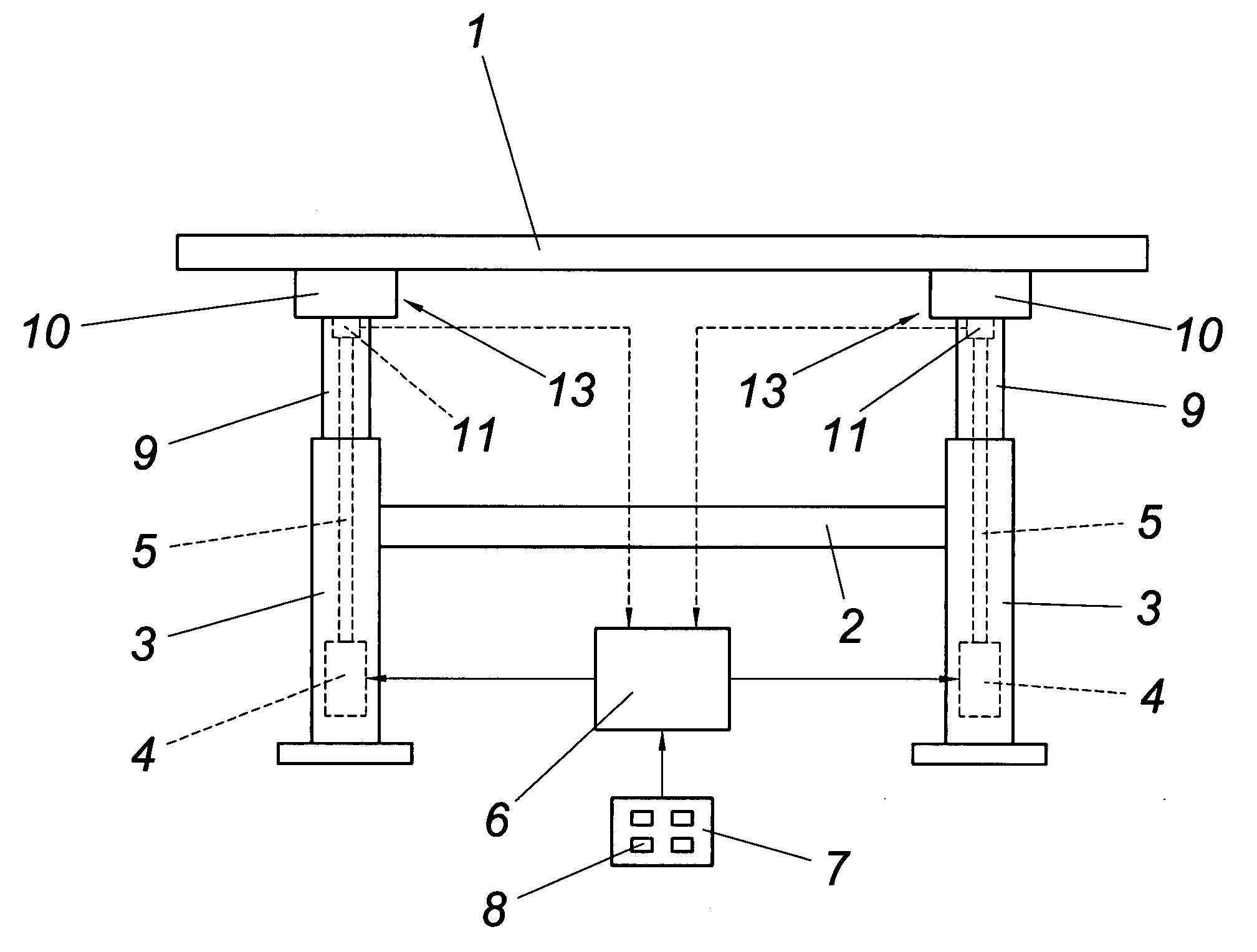
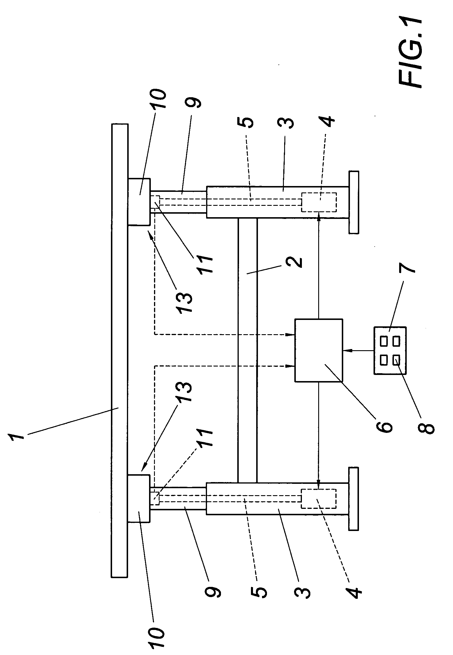
[0011] The work-table according to FIG. 1 comprises a table board 1 which is carried by a frame 2, comprising telescopic legs 3 for height adjustment of the table board 1. Said telescopic legs 3 are adjustable in their length with the help of electric motors 4. For this purpose the motors 4 each drive an actuating drive 5, e.g. a spindle drive or a toothed rack. A control device 6 is provided for controlling the motors 4, which control device can be triggered via an input unit 7 and forms a conventional entrance panel 8 for operating the work-table.

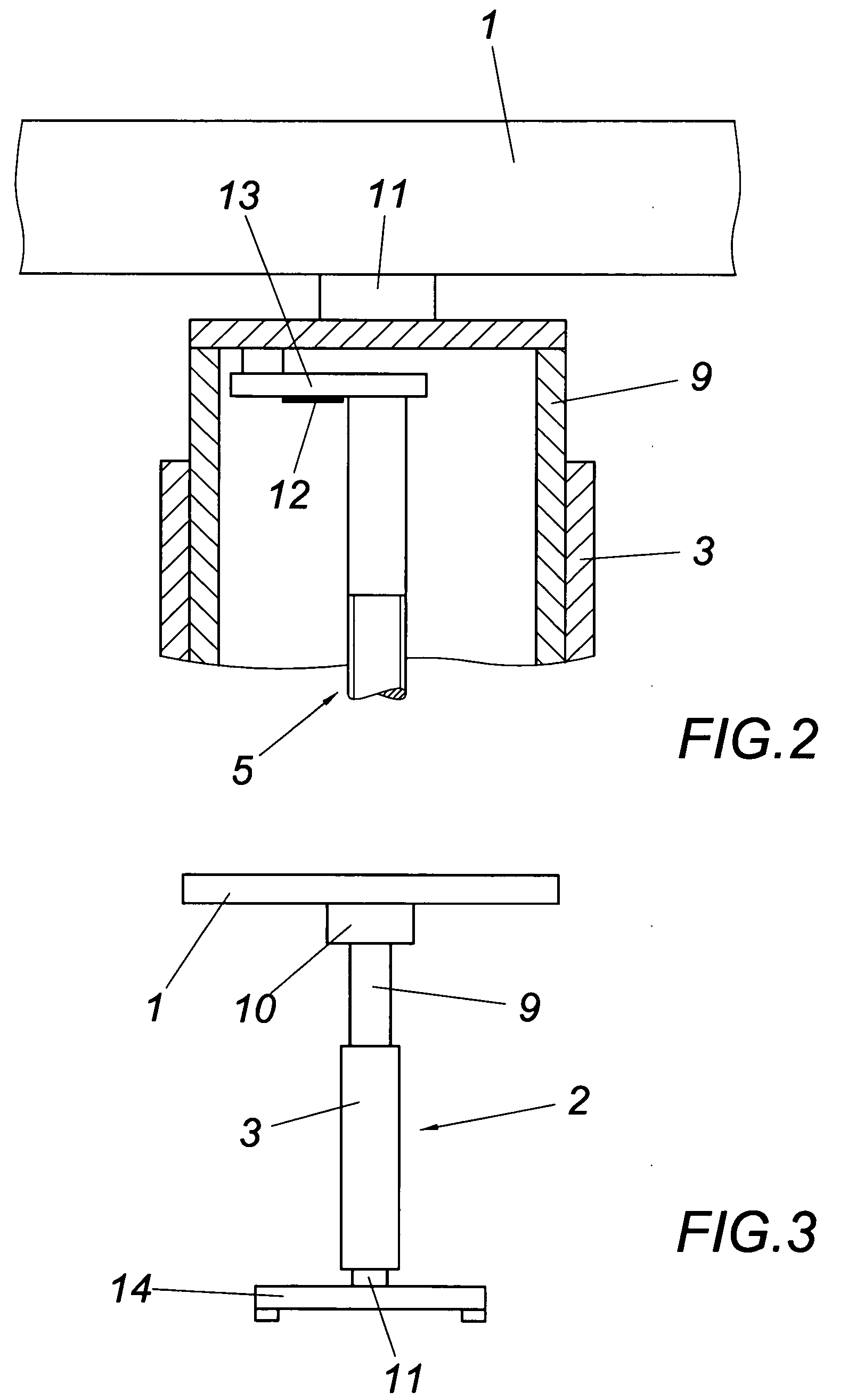
[0012] The supports 10 of table board 1 which are joined to the retractable adjusting part 9 of the telescopic legs 3 are supported via force transducers 11 on the actuating drives 5. The force transducers 11, e.g. load cells or piezoelectric elements, supply the control device 6 with signals which depend upon the loading of the table board 1, so that the motors 4 can be triggered depending on the loading of the table board 1 in order to...


PUM

PropertyMeasurementUnit
Heightaaaaaaaaaa

Abstract

A work-table is described, comprising a frame (2) which is especially adjustable with respect to its height and for whose adjustment there is provided at least one electric motor (4) with a control device (6) acting upon an actuating drive (5). In order to provide advantageous constructional conditions it is proposed that at least one load-dissipating part (13) of the frame (2) is provided with a wire resistance strain gauge (12) or is supported on a force transducer (11), and that the wire resistance strain gauge (12) or the force transducer (11) triggers the control device (6) for the motor (4) depending on the loading of the load-dissipating part (13).

Description

1. FIELD OF THE INVENTION [0001] The invention relates to a work-table, comprising a frame which is especially adjustable with respect to its height and for whose adjustment there is provided at least one electric motor with a control device acting upon an actuating drive. 2. DESCRIPTION OF THE PRIOR ART [0002] There is a likelihood in work-tables with a frame which can be adjusted in its height by at least one actuating drive driven by a motor that during the adjustment of the frame an obstruction in the path of the adjustment is hit, leading to an endangerment of the obstruction, as also the work-table or items situated on the work-table when the electromotor is not switched off. In order to detect such obstructions and thus avoid injuries it is known (AT 410 626 B) to connect the control device for the motor to a transducer for the motor load, so that upon exceeding a predetermined motor load the motor can be reversed in its direction of rotation by a control device and can be sw...

Claims


Application Information

Patent Timeline
IPC IPC(8): B23K1/06
CPCA47B9/00B25H1/16A47B2200/006
Inventor KOCH, WALTERLUKAS, STEFAN
Owner LOGICDATA ELECTRONICS & SOFTWARE
Learn More