
Methods, apparatuses and articles for automatic data collection devices, for example barcode readers, in cluttered environments

a data collection device and barcode reader technology, applied in the field of automatic data collection devices, can solve the problems of difficult operation of the device, inability to ensure the operator, and the use of adc devices such as machine-readable symbol readers, so as to facilitate image processing, enhance the illumination of a portion, and enhance the resulting image

Active Publication Date: 2006-11-23
INTERMEC IP
View PDF28 Cites 46 Cited by
  • Summary
  • Abstract
  • Description
  • Claims
  • Application Information

AI Technical Summary

Benefits of technology

[0017] In yet still another aspect, the methods and apparatuses may adjust the optical characteristics of a sensor such as an optical subsystem that focuses an image on an imager to enhance the resulting image and facilitate processing of the image, for example, the decoding of machine-readable symbols such as barcode symbols.
[0020] In still a further aspect, the methods and apparatuses may capture multiple objects on single scan, allowing the sequential decoding of selected objects without requiring further image acquisition. The number of objects sequentially decoded may be user configurable.

Problems solved by technology

The successful adoption and use of ADC devices such as machine-readable symbol readers face a number of problems.
For example, such devices may be difficult to operate by a novice, particularly where the device is handheld and requires the operator to correctly space the machine-readable reader with respect to the item bearing the machine-readable symbol to be read.
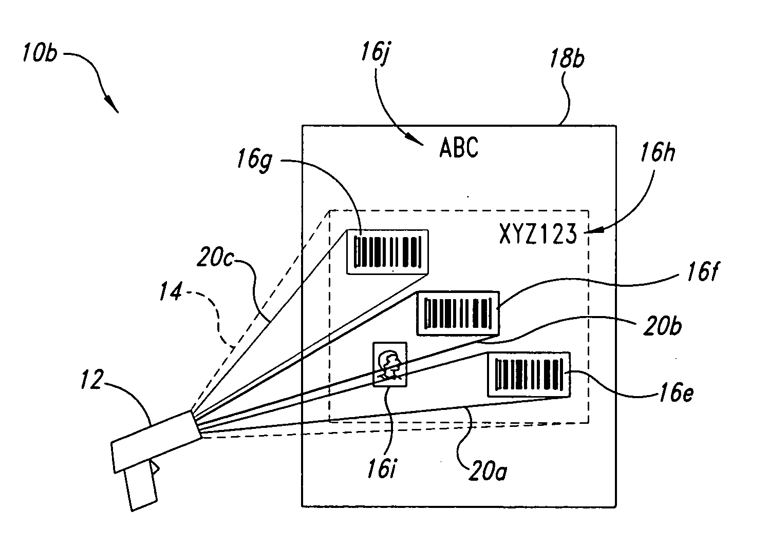
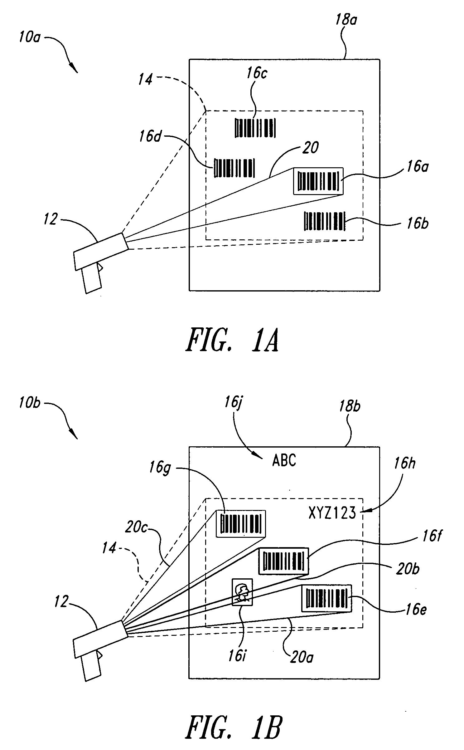
Another problem occurs when the machine-readable symbol reader is used in a crowded environment, for example where two or more objects may be within the field-of-view of the machine-readable symbol reader.
In such a situation, the operator typically will not be certain which one of the objects the machine-readable symbol reader will decode.

Method used


Image

  • Methods, apparatuses and articles for automatic data collection devices, for example barcode readers, in cluttered environments
  • Methods, apparatuses and articles for automatic data collection devices, for example barcode readers, in cluttered environments
  • Methods, apparatuses and articles for automatic data collection devices, for example barcode readers, in cluttered environments

Examples


examples of specific

Indicators

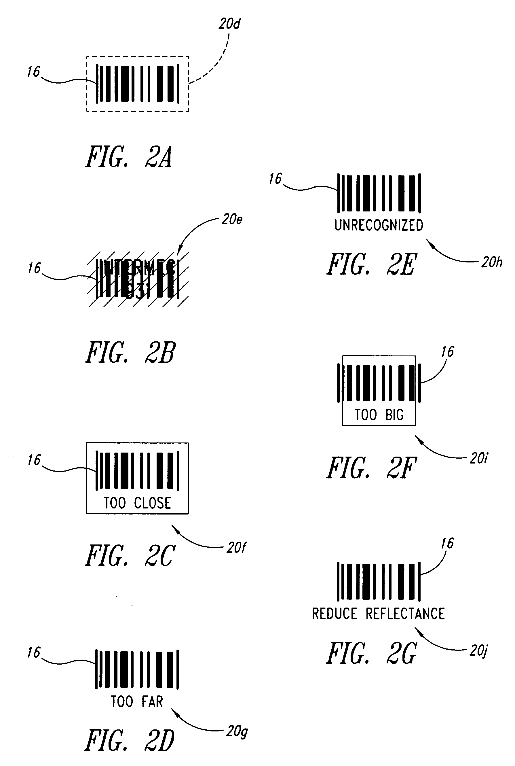
[0055]FIG. 2A shows an indicator 20d encompassing a machine-readable symbol 16. The indicator 20d may take the form of a broken line geometric pattern, such as a box, with the elements of the pattern being sequentially turned ON and OFF to achieve a marqueeing effect similar to that used in computer displays and on theater marquees. As discussed above, the rate at which the elements of the pattern are flashed may correspond to a rank or order of the associated machine-readable symbol 16. Thus, the highest ranked machine-readable symbol may marquee or sequentially flash at the highest rate, while indicators associated with successively lower ranked machine-readable symbols will be marqueed at a progressively lower rates.

[0056]FIG. 2B shows an indicator 20e associated with a machine-readable symbol 16. The indicator 20e may include text such as alphabetic and / or numeric characters that provide information about the associated machine-readable symbol 16. For example, the tex...


PUM


Abstract

A reader such as a barcode reader identifies at least one potential target such as a barcode symbol in its field-of-view, and projects or transmits an indicator toward or proximate the potential target containing information about the respective potential target. Such information may include which target is currently active, the symbology in which the target is encoded, the relative position of the reader with respect to the target, the ability of the reader to decode the target, and / or ranked or sorted order information regarding the target and neighboring targets. The reader may rank, sort, prioritize or otherwise determine order based on various parameters, including symbology, position in field-of-view, size, etc., and may base such on past history of the reader and / or user, and may weight such.

Description

CROSS-REFERENCE TO RELATED APPLICATION [0001] This application claims the benefit under 35 U.S.C. § 119(e) of U.S. Provisional Patent Application No. 60 / 681,779, filed May 17, 2005.BACKGROUND OF THE INVENTION [0002] 1. Field of the Invention [0003] The methods, apparatuses and articles described herein generally relate to automatic data collection (ADC) devices such as readers capable of reading automatic data collection media, for example optically reading machine-readable symbols (e.g., barcode symbols, area or matrix symbols, or stacked symbols). In particular, the methods, apparatuses and articles described herein facilitate machine-readable symbol acquisition in a cluttered environment, for example where two or more objects such as machine-readable symbols are in the field-of-view of the machine-readable symbol reader. [0004] 2. Description of the Related Art [0005] The ADC field is generally directed to the use of devices for automatically capturing data typically encoded in m...

Claims


Application Information

Patent Timeline
IPC IPC(8): G06K7/10
CPCG06K7/10851
Inventor RAY, JIM T.KOHTZ, ROBERT A.DANT, MICHAELHUNT, JEFFREY M.
Owner INTERMEC IP
Learn More