
Transportable pumping unit and method of fracturing formations

a technology of transportable pumping units and fracturing formations, which is applied in the direction of containers discharging from non-pressured vessels, positive displacement liquid engines, non-pressured vessels, etc., can solve the problems of heavy transportable units exceeding, high labor intensity, and high pressure on the environment, so as to achieve low impact and reduce the effect of environmental impa

Inactive Publication Date: 2006-11-23
CENTURY OILFIELD SERVICES
View PDF2 Cites 246 Cited by
  • Summary
  • Abstract
  • Description
  • Claims
  • Application Information

AI Technical Summary

Benefits of technology

[0015] In another embodiment, the above apparatus makes possible a low impact operation for fracturing subterranean formations with high rates of pressurized gas with a minimum number of components and a minimum impact on the environment.
[0016] In another embodiment, an improved manifold enables improved efficiency and improved ease of maintenance. More particularly, a liquid supply manifold has a plurality of connecters, one per pump head. Each connector is coupled at a union enabling one failed head to be removed without removing each other head. Further, each connector between the heads and the manifold can be oriented at an obtuse angle for aiding the flow of liquid from the manifold to the head.

Problems solved by technology

The assembly and subsequent disassembly and transport of the units to other sites following completion of fracturing or stimulation processes is costly and highly labor intensive.
Attempts to increase the volumetric capacity to meet the larger injection needs has typically resulted in heavy transportable units which exceed most weight restrictions on roads imposed by organizations such as state, provincial and federal Departments of Transportation, or which otherwise require special permitting.
The need for more units increases the manpower required to operate the units, thus adding to the already increased costs of providing additional expensive equipment.

Method used


Image

  • Transportable pumping unit and method of fracturing formations
  • Transportable pumping unit and method of fracturing formations
  • Transportable pumping unit and method of fracturing formations

Examples


Embodiment Construction

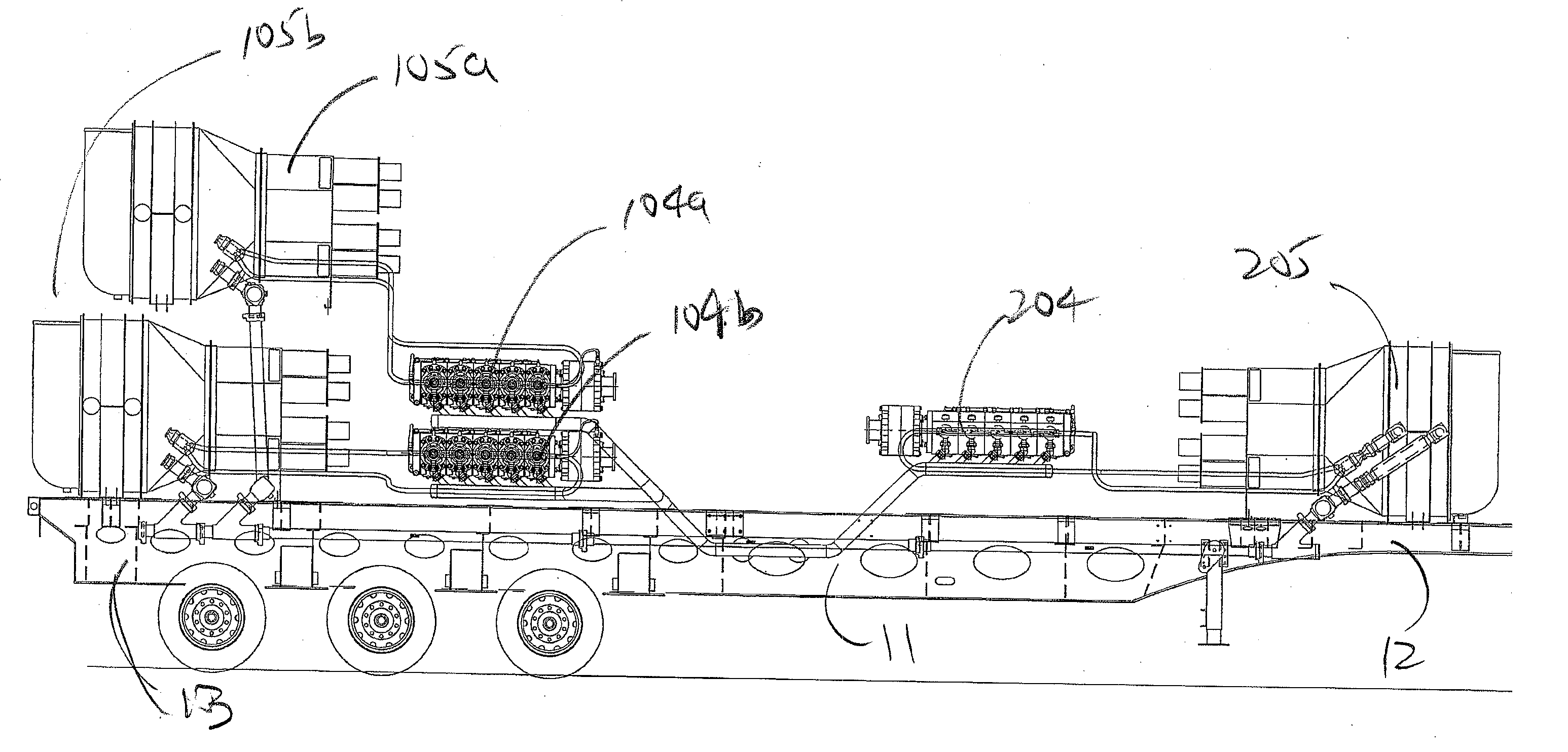
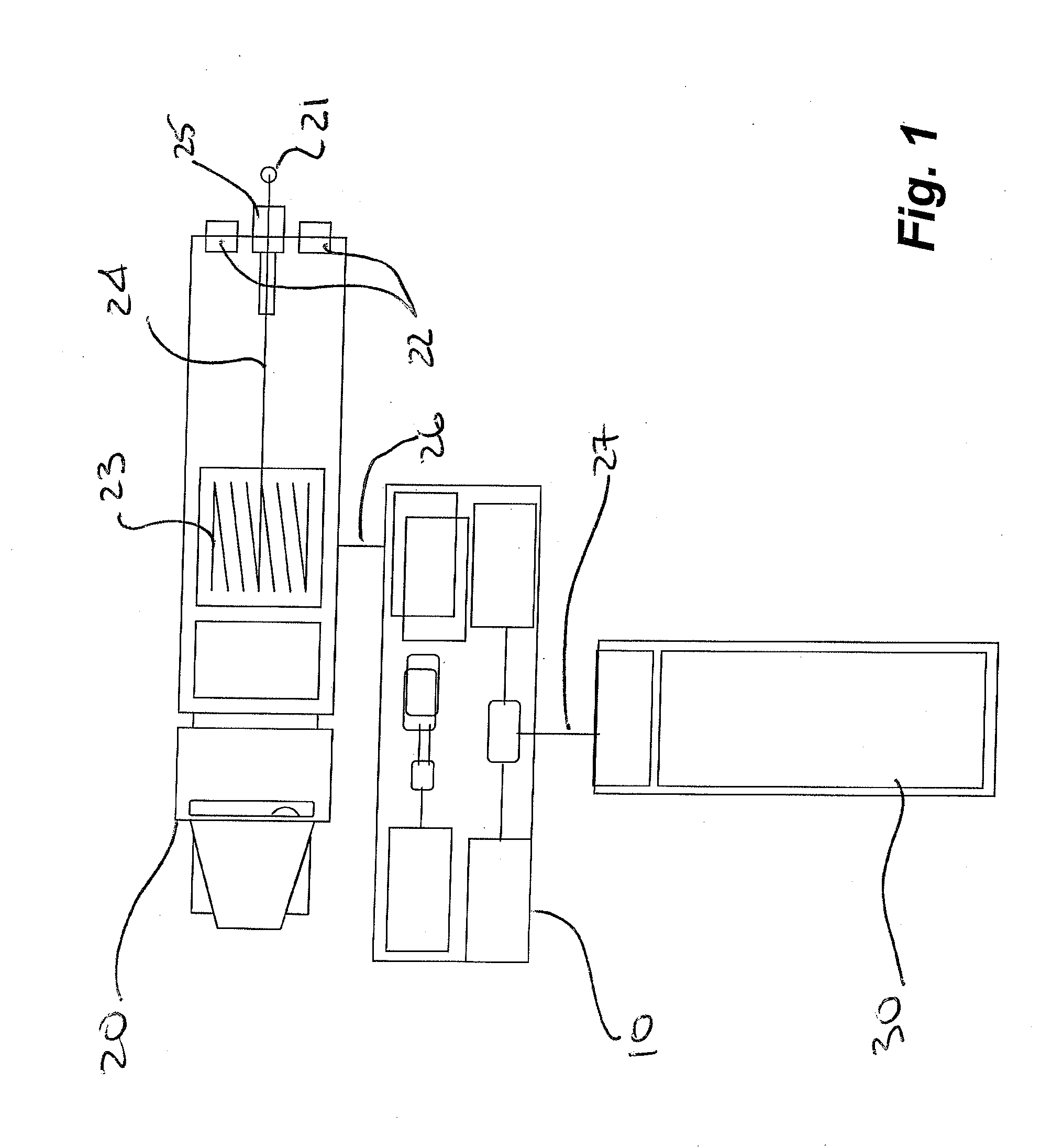
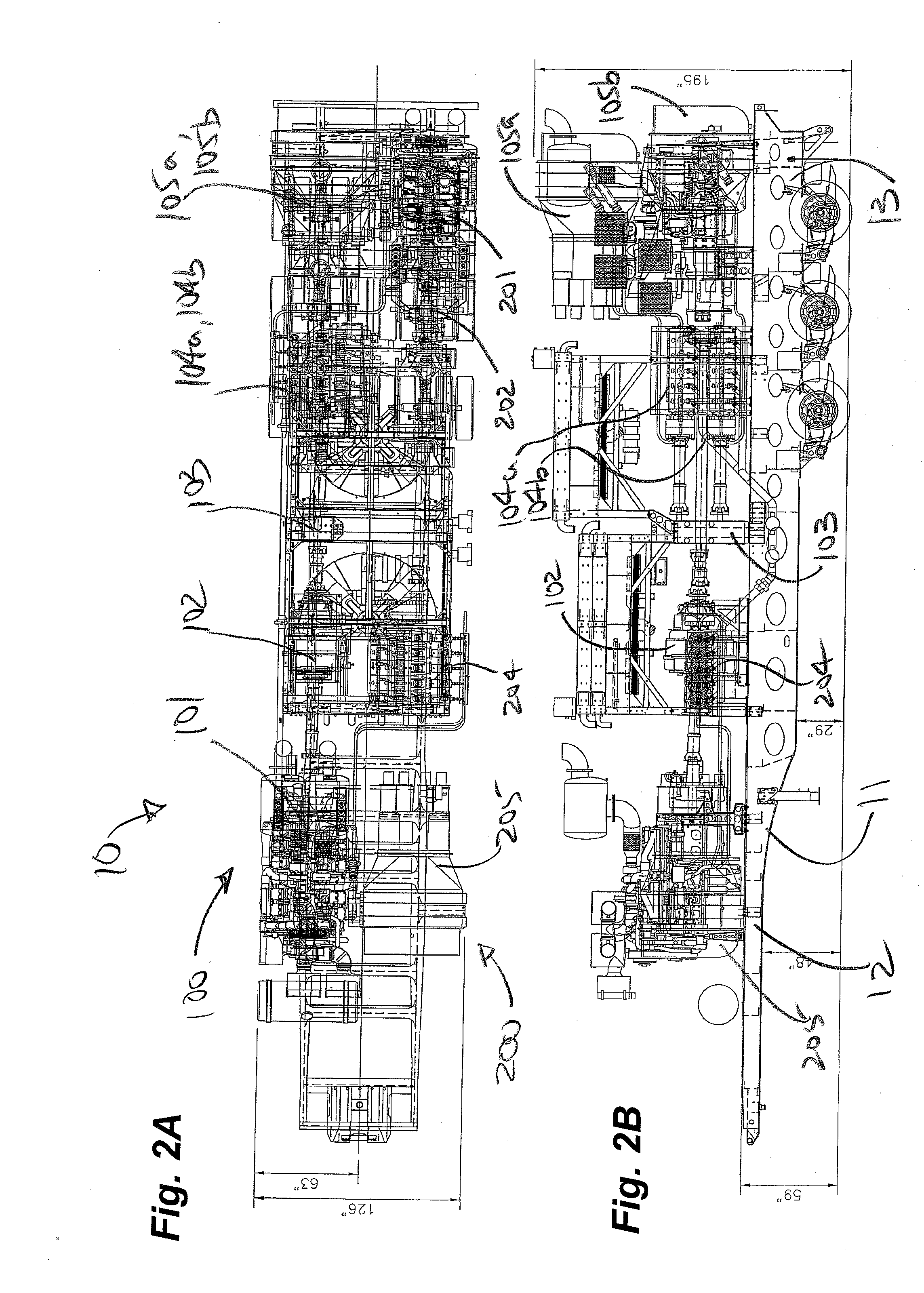
[0035] As shown in FIG. 1, a high-capacity liquefied gas pumper unit 10 can be part of a system utilizing a minimum number of components with a corresponding minimum impact on the environment and public. Fracturing of some forms of subterranean formations requires high capacities of pressurized gas. Heretofore, high capacity delivery systems suitable for NGC fracturing operations have requires two or even three separate pumper units to supply sufficient vaporized and pressured gas. The same can now be accomplished with one unit 10 according to the present invention. As discussed, one cannot merely use larger equipment as the limitation is the ability to legally deliver the heavy equipment over roads under a variety of conditions, and with minimum on site assembly. Ideally an entire on site operation is measured in hours and every lost moment is critical.

[0036] With reference to FIG. 1, the major components of a system according to an embodiment of the invention, such as that used f...


PUM


Abstract

A high capacity pumper for liquefied gas incorporates multiple pumping systems distributed in a parallel arrangement and in opposing orientation on a transportable platform such as a trailer. Vaporizers incorporate a burner control system utilizing a primary set of burners operating a baseline and a secondary set of burners providing fine regulating control. A system for fracturing formations is now possible using a minimum number of components including the high capacity pumper, a coiled tubing rig and a source of liquefied gas. An improved manifold for a cryogenic plunger pump includes unions and angled connectors between a supply conduit and each of a plurality of pump heads.

Description

FIELD OF THE INVENTION [0001] Embodiments of the invention relate to transportable units and systems for providing large volumes of pressurized inert gases, particularly nitrogen such as use in the petroleum industry and more particularly to trailer mounted nitrogen vaporization and pumping units. BACKGROUND OF THE INVENTION [0002] In some industries there is a need for high volumes of pressurized gases. For example, in the oil and gas industry, it is known to use pressurized inert gases, such as nitrogen, for enhanced recovery of hydrocarbon resources such as through fracturing and stimulation of coal bed methane for production of natural gas from coal (NGC). Liquefied nitrogen is pressurized, vaporized to a gas and injected down a well at high pressure to hydraulically fracture a coal seam bearing the natural gas. Examples of NGC reserves are those located in western Canada. While the embodiments herein are described in the context of the oil and gas industry, other applications b...

Claims


Application Information

Patent Timeline
Patent Type & Authority Applications(United States)
IPC IPC(8): F17C9/02
CPCF04B15/08F04B37/18F04B17/06F04B17/05
Inventor ANDREYCHUK, MARK T.
Owner CENTURY OILFIELD SERVICES
Learn More