Method and system integrating combined cycle power plant with a solar rankine power plant

Inactive Publication Date: 2006-11-23
MARKRON TECH
View PDF21 Cites 82 Cited by
  • Summary
  • Abstract
  • Description
  • Claims
  • Application Information

AI Technical Summary

Benefits of technology

[0013] Thus, in accordance with at least one embodiment, a method for generating power can be provided. The method can comprise generating a heated reheat of a first working fluid in a first power generation system and vaporizing a second working fluid liquid in a second power generation system to form a second working fluid vapor. The method can also comprise transferring energy from the reheat of the first working fluid to the second working fluid vapor thus increasing a temperature and a pressure of the second working fluid vapor of the second power generation system.
[0014] In accordance with at least one embodiment, a method to increase the thermodynamic availability of a first working fluid vapor having a first temperature and a first pressure can be provided. The method can comprising the steps of transferring the first working fluid vapor to a superheater and transferring a second working fluid vapor to the superheater, the second working fluid vapor having a second temperature that is lower than the first temperature and a second pressure that is higher than the first pressure. The method can also comprise transferring heat energy in the superheater from the first working fluid vapor to the second working fluid vapor to increase the temperature and pressure of the second working fluid vapor.

Problems solved by technology

This is due to the limitations of the oils used in solar thermal arrays for transporting thermal energy from the solar array to the boiler.
For example, very high temperature steam (1200° F.) at atmospheric pressure cannot be used to drive an expansion turbine.
Thus, even though the steam at 1200° F. and atmospheric pressure contains a large amount of thermal energy, this energy is not “available” for use in an expansion turbine; expansion turbines cannot convert thermal energy into shaft power.

Method used


Image

  • Method and system integrating combined cycle power plant with a solar rankine power plant
  • Method and system integrating combined cycle power plant with a solar rankine power plant
  • Method and system integrating combined cycle power plant with a solar rankine power plant

Examples


Embodiment Construction

[0023] The following discussion describes in detail several embodiments of power generation systems and various aspects of these embodiments. This discussion should not be construed, however, as limiting the present inventions to those particular embodiments. Practitioners skilled in the art will recognize numerous other embodiments including those that can be made through various combinations of the aspects of the illustrated embodiments.

Combined Cycle Power Generation System

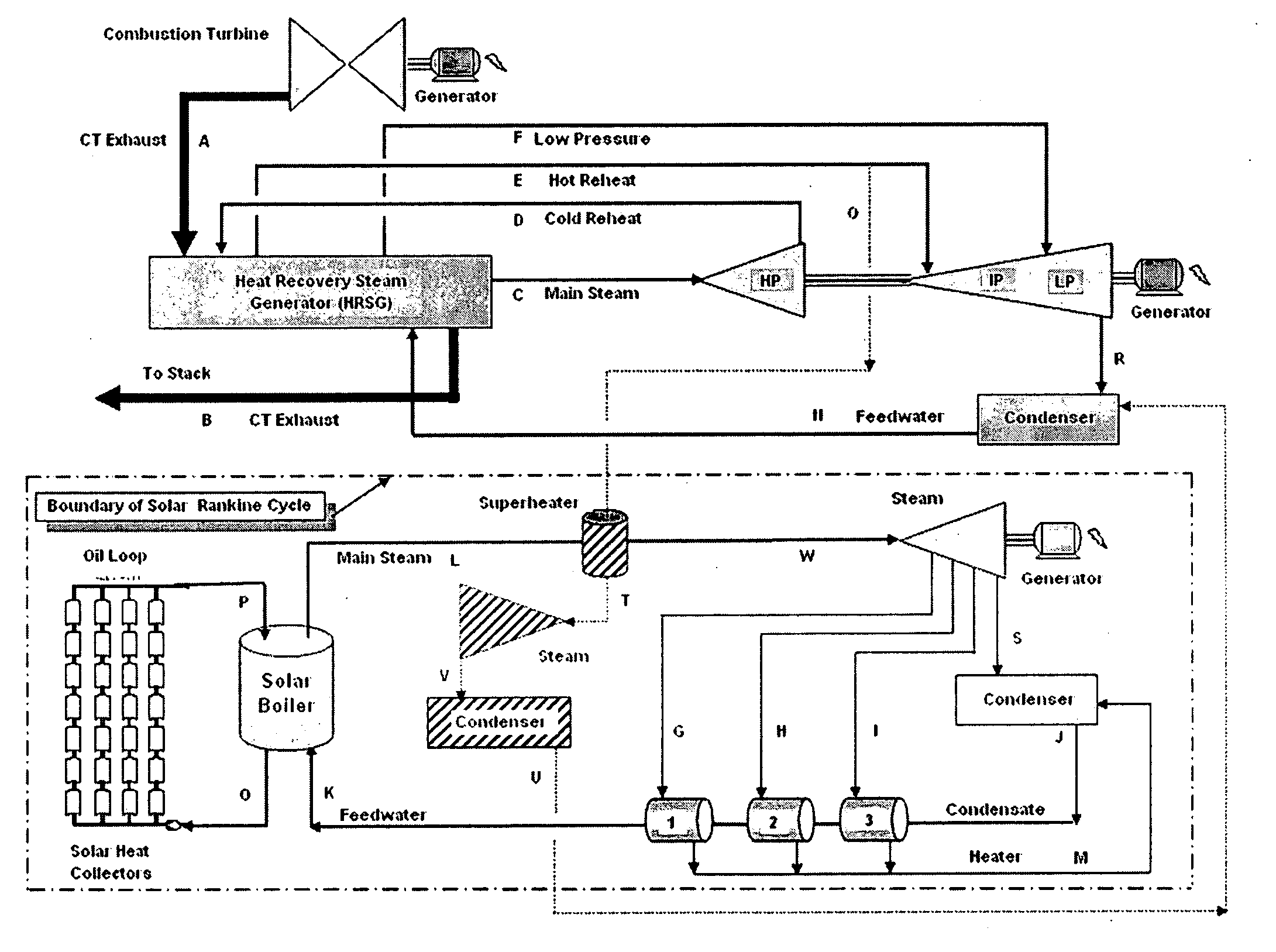
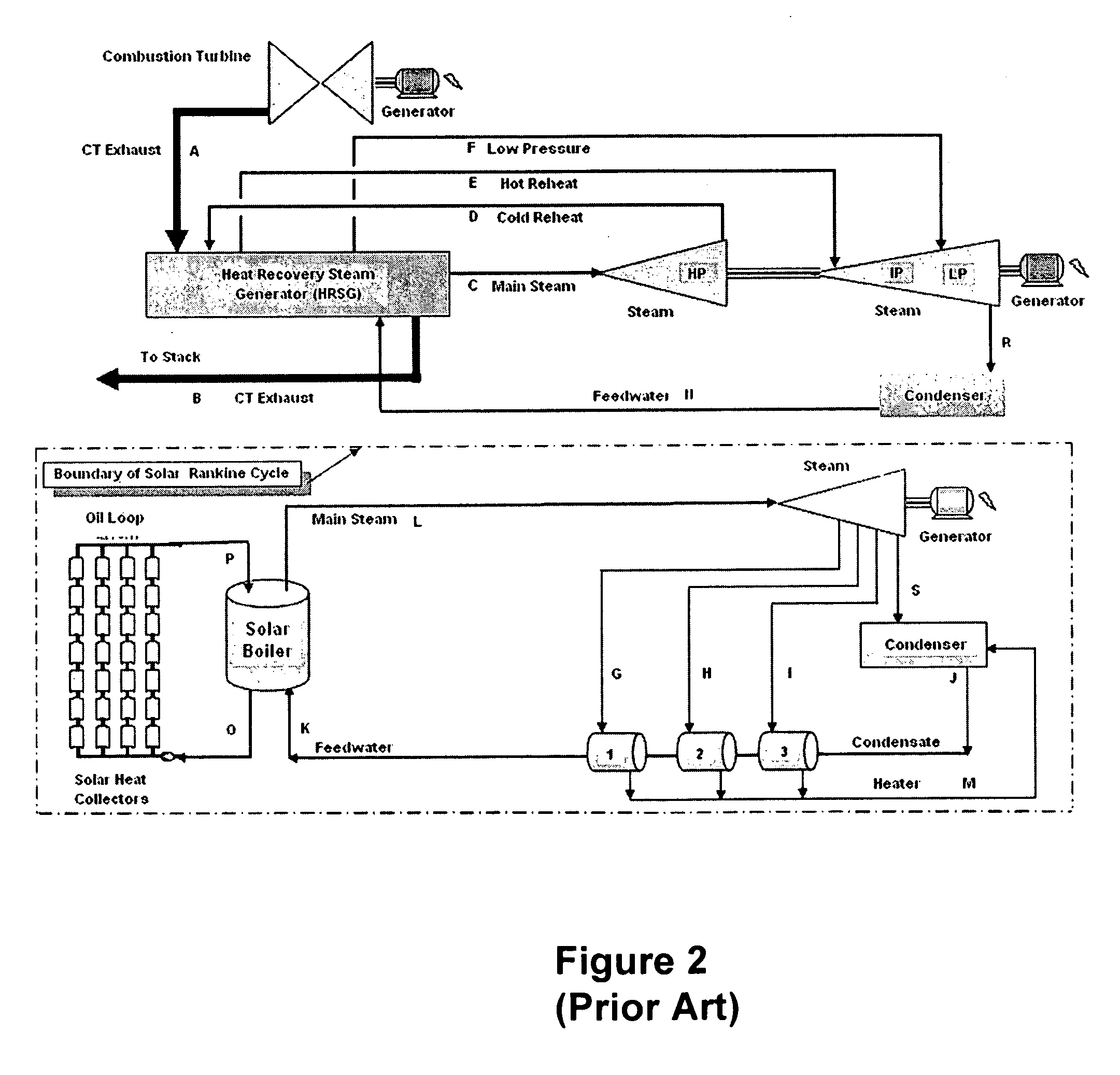
[0024] A three pressure combined cycle with reheat is used in the embodiments of combined cycle power generation systems discussed herein, although other combined cycles and other configurations of multiple pressure combined cycles can also be used. An illustrative three pressure combined cycle is illustrated in the upper portion of FIG. 2.

[0025] In the illustrated combined cycle power generation system, a Brayton cycle combustion turbine is used as a topping cycle with the exhaust (A) of the combustion tur...


PUM


Abstract

A combined cycle power generation system can be combined with a solar Rankine power generation system such that the integrated system has improved power generation efficiency over two stand-alone systems. Relatively high temperature, low pressure reheat from the combined cycle power generation system can be used, through, for example, a superheater, to raise the temperature and pressure of a working fluid in a solar Rankine power generation system. The resulting integrated system has enhanced efficiencies as compared with stand-alone systems.

Description

CROSS-REFERENCE TO RELATED APPLICATIONS [0001] This application claims the benefit of U.S. Provisional Patent Application No. 60 / 665,048, entitled “Method to Integrate Fossil Fueled Combined Cycle Power Plant with a Solar Rankine Power Plant,” filed on Mar. 25, 2005; and U.S. Provisional Patent Application No. 60 / 693,111, entitled “Method to Integrate Fossil Fueled Combined Cycle Power Plant with a Solar Rankine Power Plant Using a Common Steam Turbine,” filed on Jun. 23, 2005. These provisional applications are incorporated by reference herein in their entireties.BACKGROUND OF THE INVENTION [0002] 1. Field of the Invention [0003] The application relates generally to systems and methods for power generation and more specifically to systems and methods for integrating a fossil fueled combined cycle power generation system with a solar Rankine power generation system with enhanced power generation efficiency. [0004] 2. Description of the Related Art [0005] Solar thermal generation can...

Claims


Application Information

Patent Timeline
IPC IPC(8): F03G6/00F01K13/00B60K16/00B60L8/00
CPCF01K23/10F02C6/18Y02E20/16Y02E10/46F03G6/005Y02T10/7072
Inventor KINCAID, RONALD FARRISSKOWRONSKI, MARK JOSEPH
Owner MARKRON TECH
Why Eureka
Try Eureka