Rotary axial fan assembly

a technology of rotary axial fans and fan assemblies, which is applied in the direction of machines/engines, mechanical equipment, liquid fuel engines, etc., can solve the problems of increased sound level of the fan assembly, lack of performance and efficiency of conventional rotary axial fans for internal combustion engine cooling systems, etc., and achieves the effect of reducing sound output and enhancing fluid flow efficiency

Inactive Publication Date: 2006-11-16
EMP ADVANCED DEVMENT
View PDF25 Cites 38 Cited by
  • Summary
  • Abstract
  • Description
  • Claims
  • Application Information

AI Technical Summary

Benefits of technology

[0012] Another aspect of the present invention is to provide a stator fan for a rotary axial fan assembly. The stator fan includes a shroud that is adapted to be mounted proximate to a heat exchanger for conveying a flow of fluid through the heat exchanger and the shroud. An array of stator fan blades extend inward from the shroud and support a hub oriented generally centrally within the shroud. The hub is adapted to receive a rotary axial fan. Each stator fan blade has a generally uniform thickness oriented generally perpendicular to a direction of fluid flow. Each stator fan blade is generally linear and is oriented offset from a radial direction relative to the hub. The thickness and orientation of the stator fan blades enhance the efficiency of fluid flow and thereby provide a reduced sound output from the rotary axial fan assembly.

Problems solved by technology

Stator fan blades, however, typically increase an associated sound level of the fan assembly.
Conventional rotary axial fans for internal combustion engine cooling systems are lacking in performance and efficiency.

Method used


Image

  • Rotary axial fan assembly
  • Rotary axial fan assembly
  • Rotary axial fan assembly

Examples


Embodiment Construction

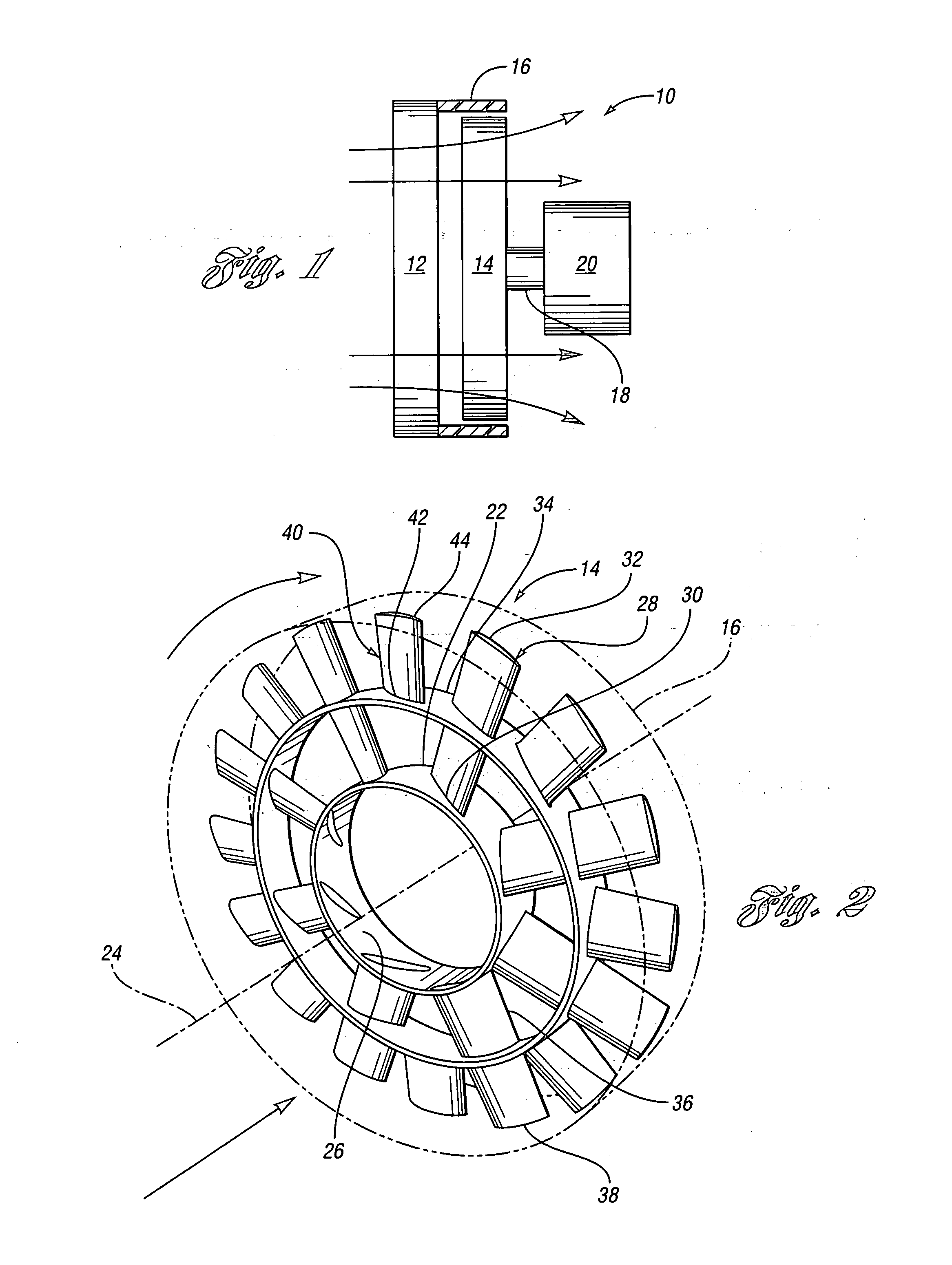
[0025] With reference now to FIG. 1, an internal combustion engine cooling system is illustrated schematically and indicated generally by reference numeral 10. The system includes a radiator indicated by reference numeral 12 that receives heated coolant from the internal combustion engine (not shown) and transfers heat from the coolant to air that passes therethrough. Air is passed through the radiator by movement of the vehicle and air is forced by a rotary axial fan 14. Commonly, an external shroud 16 is provided to limit the moving of air to travel in an axial direction. The shroud 16 is mounted to the radiator 12. The fan 14 is mounted to a drive member 18, which is driven by a motor 20. The motor 20 drives the drive member 18 and fan 14 for forcing air through the radiator 12, shroud 16 and fan 14 thereby cooling coolant that is passed through the radiator 12.

[0026] Of course, the drive member 18 can be driven directly by the internal combustion engine by a belt drive system, ...


PUM


Abstract

The present invention provides a rotary axial fan and a stator fan for moving air through a heat exchanger for an internal combustion engine cooling system. The fan includes a hub and primary fan blades extending radially from the hub. An annular shroud is attached to the primary fan blades and supported coaxially with the central axis to limit the radial flow of air along the primary fan blades. A plurality of secondary fan blades are interposed between the primary fan blades and each have a first end attached to the annular shroud and terminate in a second end that is not attached to the hub. The stator fan includes a shroud with an array of stator fan blades supporting a hub for the radial axial fan. The size, orientation and material characteristics of the stator fan blades improve sound reduction and heat transfer of the rotary axial fan assembly.

Description

STATEMENT REGARDING FEDERALLY SPONSORED RESEARCH OR DEVELOPMENT [0001] This invention was made with Government support under Contract No. W56HZV-04-C-0020. The Government has certain rights to the invention.BACKGROUND OF THE INVENTION [0002] 1. Field of the Invention [0003] The invention relates to cooling systems, more particularly to a fan assembly utilized for moving air through a heat exchanger. [0004] 2. Background Art [0005] Motor vehicles commonly utilize heat exchangers to dissipate heat collected in the operation of the motor vehicle to the ambient air. These heat exchangers include radiators for cooling an internal combustion engine or a heater core for providing heat to a passenger compartment for climate control. [0006] Internal combustion engine cooling systems that utilize a heat exchanger may also include a rotary axial fan for enhancing the movement of air through the heat exchanger. For example, a radiator in conventional motor vehicles includes a fan rearward of th...

Claims


Application Information

Patent Timeline
Patent Type & Authority Applications(United States)
IPC IPC(8): F04D29/58
CPCF01P5/06F04D29/661F04D29/544F04D29/384F04D29/326
Inventor CARLSON, JEREMY S.PIPKORN, NICHOLAS T.STEPHENS, TODD R.
Owner EMP ADVANCED DEVMENT
Why Eureka
Try Eureka