
Method and system for extending binary image data to contone image data

Inactive Publication Date: 2006-11-16
XEROX CORP
View PDF73 Cites 21 Cited by
  • Summary
  • Abstract
  • Description
  • Claims
  • Application Information

AI Technical Summary

Benefits of technology

[0006] Conventional image path electronics may also utilize binary image paths. In this situation, if the input information is scanned in a binary manner at sufficiently high resolution, the scanned image can be reconstructed at the output with little or no perceptible loss of image quality.
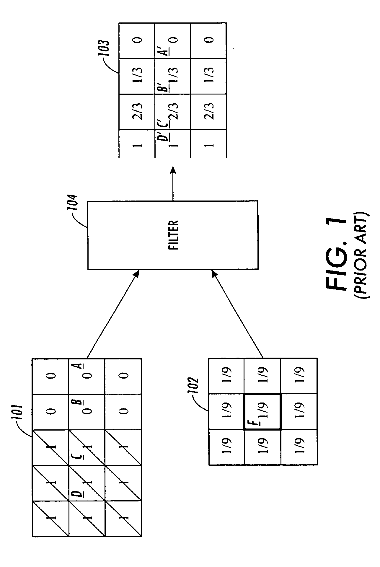
[0010] In FIG. 1, a portion of an image 101, in the form of a matrix, is shown. In the portion of the image 101, a vertical edge transitioning from black to white is shown, whereby a black region, represented by the numeric binary values “1” and slashed boxes, occupies the leftmost vertical column, and a white region, represented by the numeric binary values “0” and non-slashed boxes, occupies the center and rightmost vertical columns of the portion of the image 101. A filter kernel 102 provide a simple matrix of filter weights wherein an output pixel is the evenly weighted average of the nine pixels covered by the filter kernel 102. After a filter 104 performs the filtering operation, a portion of a output image 103 is generated.
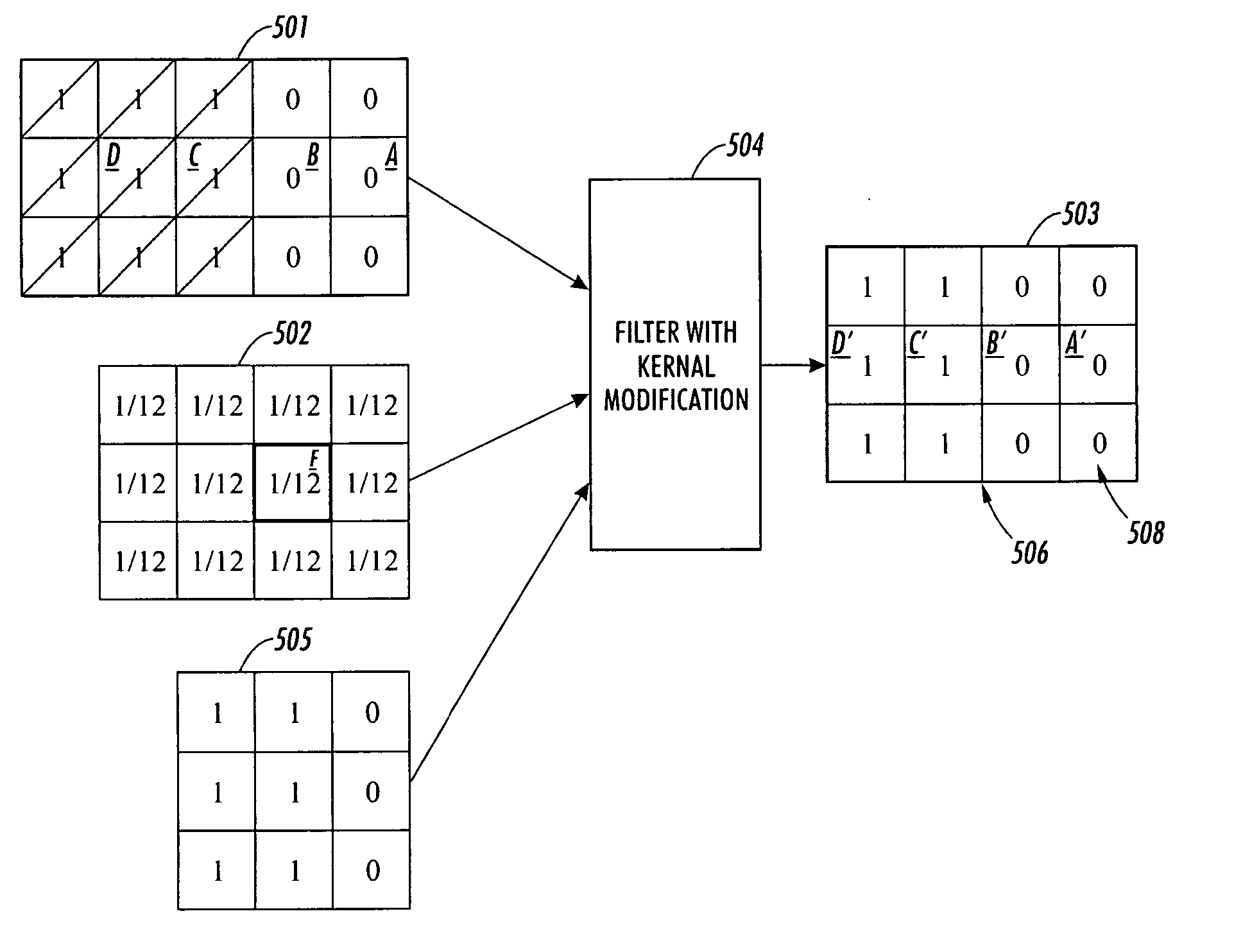
[0015] In FIG. 3, a portion of an image 301, in the form of a matrix, is shown. In the portion of the image 301, a vertical edge transitioning from black to white is shown, whereby a black region, represented by the numeric binary values “1” and slashed boxes, occupies the leftmost vertical column, and a white region, represented by the numeric binary values “0” and non-slashed boxes, occupies the center and rightmost vertical columns of the portion of the image 301. A filter kernel 302 provides a simple matrix of filter weights wherein an output pixel is the evenly weighted average of the nine pixels covered by the filter kernel 302. After a filter 304 performs the filtering operation, a portion of a output image 303 is generated.
[0025] Therefore, it is desirable to provide a system or methodology that implements a conversion of high resolution binary image data to analog that prevents the smearing of sharp edges and is substantially free of edge artifacts.

Problems solved by technology

The image path is usually one of the more complex and costly components of such digital multifunction devices.
On the other hand, there are cost constraints and perhaps performance limits on the devices or software that comprise the image path.
While such a system does an adequate job of converting the high resolution binary data to analog data, these solutions also have the deleterious effect of smearing sharp edges in the original document.
Such an effect is particularly detrimental when reproducing text and line art.
However, as demonstrated above, the conventional edge reconstruction process can generate artifacts that while less objectionable than the softening of a simple filtering process are nevertheless detrimental to the overall quality of the resulting image. FIG. 7 shows an example of how the conventional edge reconstruction process can create an artifact, ghost image 710.
Although some conventional systems have attempted to minimize the edge softening of the filter, artifacts can still be created near edges in the analog output.
These artifacts detract from the perceived quality of the output.

Method used


Image

  • Method and system for extending binary image data to contone image data
  • Method and system for extending binary image data to contone image data
  • Method and system for extending binary image data to contone image data

Examples


Embodiment Construction

[0049] For a general understanding, reference is made to the drawings. In the drawings, like references have been used throughout to designate identical or equivalent elements. It is also noted that the drawings may not have been drawn to scale and that certain regions may have been purposely drawn disproportionately so that the features and concepts could be properly illustrated.

[0050] In describing a method for reconstructing an analog image from a high resolution binary representation of an original object, the following description assumes that the high resolution binary image is accompanied by a parallel image wherein each pixel of the binary image is matched with a bit, called a “tag bit” that indicates whether the bit in the image represents a pixel at a density edge in the original image. The methods for determining how a tag bit is generated are conventional and well known to those skilled in the art. Such methods include matching some region of the image against a set of ...


PUM


Abstract

A method and system converts a binary image into an analog image by first tagging pixels that are part of edges in the digital image and using this tagging information to eliminate such tagged pixels from the digital filtering process. The elimination of such tagged pixels from the digital filtering process substantially eliminates artifacts near the edges, thereby reducing any distraction from the perceived quality of the output image.

Description

BACKGROUND AND SUMMARY [0001] Digital multifunction reprographic systems are now well known and have replaced optical reprographic systems as a way to reproduce images. In these conventional digital multifunction reprographic systems, a scanner accepts a document to be copied and converts the document into electronic image(s). These images, usually in the form of pages, are then passed to a central control unit which may re-order or reorganize these pages and then, depending on the request of the user of the device, send the pages or images to a destination. Often this destination is an attached printing unit which makes one or more copies of the original document. [0002] However, these conventional devices perform many other functions besides simple copying. The central control unit is usually equipped with a combination of hardware and software elements that enable it to accept input from other sources. The other sources may include some sort of network interface and / or an interfa...

Claims


Application Information

Patent Timeline
IPC IPC(8): G06K9/40H04N1/40
CPCG06T7/0083G06T2207/20192G06T5/20G06T5/003H04N1/4092G06T7/12G06T5/73
Inventor MCCANDLISH, PETER D.
Owner XEROX CORP
Learn More