CCFL device with a gaseous heat-dissipation means
a fluorescent lamp and gaseous heat dissipation technology, which is applied in cold cathode manufacturing, electrode system manufacturing, electric discharge tube/lamp manufacturing, etc., can solve the problems of hcfl having tungsten wire easily breaking, and hcfl a relatively short life lighting device. achieve the effect of high intensity illumination
- Summary
- Abstract
- Description
- Claims
- Application Information
AI Technical Summary
Benefits of technology
Problems solved by technology
Method used
Image
Examples
embodiment 1
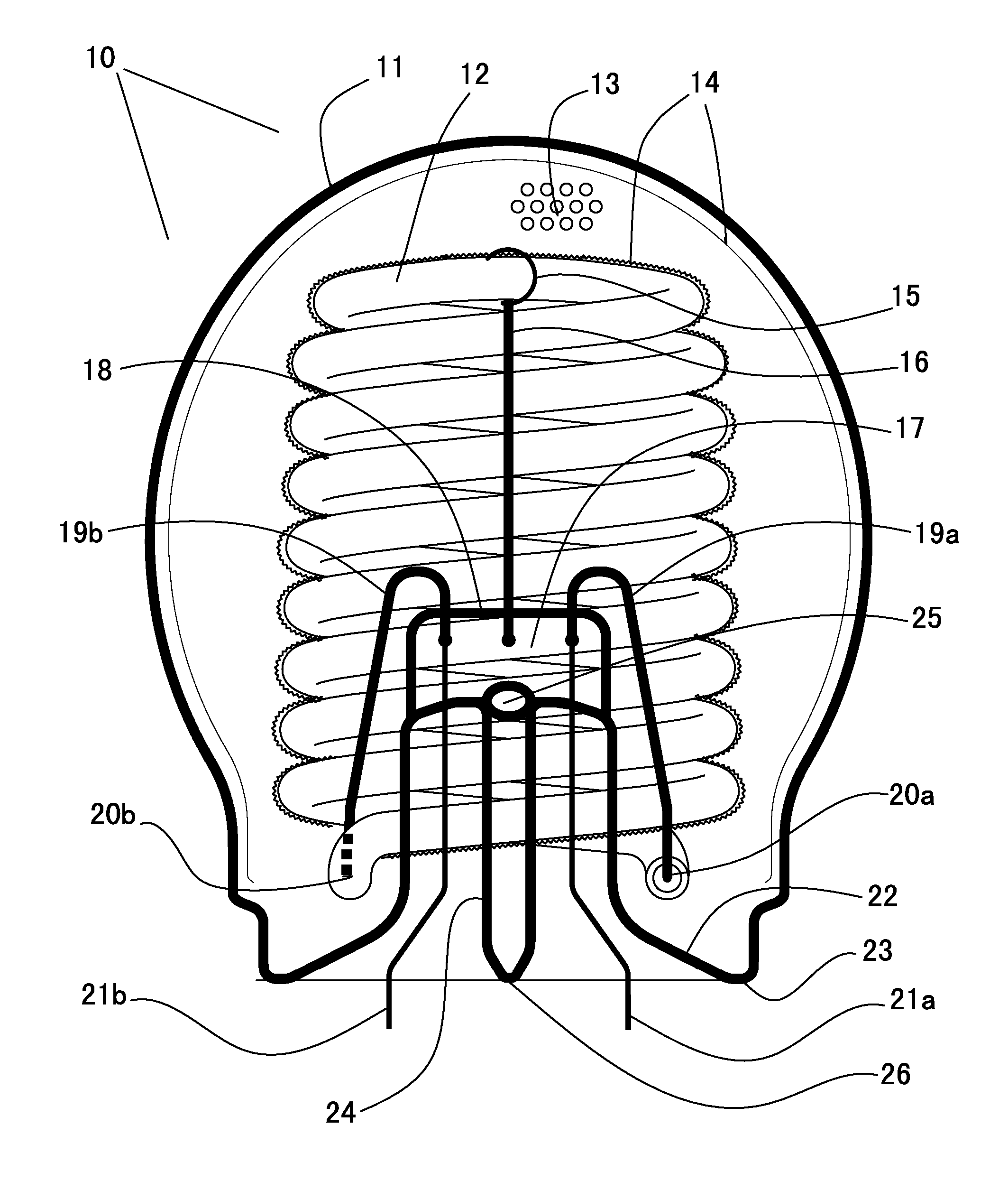
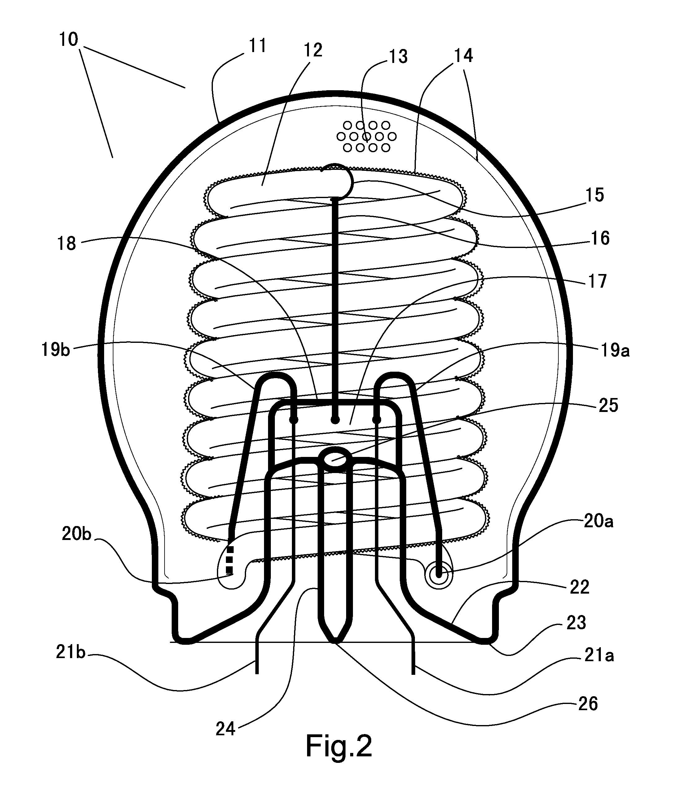
[0096] The first embodiment of the present invention provides a novel heat dissipation means for an CCFL device that is comprising: an hermetically sealed light-transmitting container housing at least one CCFL filament inside; an electronic driver providing high-frequency and high-voltage electricity is electrically connected to the electrodes of the CCFL filament, and is also connected to a lamp base that receives external electricity from a electrical socket, and said container is filled with a high thermal conductivity gas that has better thermal conductivity than air, so that the heat generated from the CCFL filament can be dissipated swiftly into the atmosphere through the surface of the light-transmitting container.
[0097] In the embodiment immediately above, and in other embodiments described below, there are many obvious variations for forming said CCFL device. For instance, the electronic driver can be a DA / AC or AC / AC converter, i.e., the input electricity current can be e...
embodiment 2
[0108] Another embodiment of the present invention provides a novel method stopping the helium or hydrogen gases leaking away from the light-transmitting container, and also stopping them from diffusing into the inside of the CCFL lamp filament which is of lower partial helium or hydrogen pressure than the inside of the light-transmitting container. Helium and hydrogen can normally diffuse through the glass container and the hermetical seals between the glass container and other lamp body surfaces. According to the present invention, soda lime glasses is used for the light-transmitting container and for the glass envelope of the CCFL filament, as the helium and hydrogen permeation rates through soda lime glass are several thousand times less than those through quartz, borosilicate and Pyrex glass under room temperature. Moreover, for the other parts of the lamp body, such as the container connection member, metal such as aluminum or copper is preferred, as the helium and hydrogen ga...
embodiment 3
[0112] Another embodiment of the present invention provides a novel means to affix the CCFL lamp filament within the light-transmitting container in a secured and vibration-proof manner, and at the same time, to allow air be evacuated from, and a high thermal conductivity gas be filled inside said container. This is accomplished by affixing the CCFL lamp filament to a traditional lamp foot that has been used for the incandescent light bulbs for over a century. A lamp foot is formed from a short and hollow glass tube of outer diameter 5-10 mm and inner diameter 3-7 mm so that the tube body is about 1 mm thick. Owing to the massive demand, automated machines are available to make lamp foots in large volumes and at low cost, and existing automated machines for bonding lamp foots to the light-transmitting containers are abundant.
[0113] Commercially available lamp foots have many different formats, but all have three common features, i.e., (1) an inner glass exhaust tube along its axis,...
PUM
 Abstract
Description
Claims
Application Information
 - R&D
- Intellectual Property
- Life Sciences
- Materials
- Tech Scout
- Unparalleled Data Quality
- Higher Quality Content
- 60% Fewer Hallucinations
Browse by: Latest US Patents, China's latest patents, Technical Efficacy Thesaurus, Application Domain, Technology Topic, Popular Technical Reports.
© 2025 PatSnap. All rights reserved.Legal|Privacy policy|Modern Slavery Act Transparency Statement|Sitemap|About US| Contact US: help@patsnap.com


