
Hydrostatic bearing for linear motion guidance

Inactive Publication Date: 2006-11-09
MFR & TRADERS TRUST COMPANY AS AGENT
View PDF37 Cites 10 Cited by
  • Summary
  • Abstract
  • Description
  • Claims
  • Application Information

AI Technical Summary

Benefits of technology

[0011] End sealing structures are provided on end portions of the bearing carriage. At least one edge of the end sealing structures engages the bearing rail to prevent hydrostatic fluid from leaking from between the bearing carriage and the bearing rail. Side sealing structures are provided on side portions of the bearing carriage and extend at least a portion of the length of the bearing carriage. At least one edge of the side sealing structure engages the bearing rail to prevent hydrostatic fluid from leaking from between the bearing carriage and the bearing rail.
[0014] The bearing carriage includes a plurality of self-compensating bearing pads provided on surfaces that oppose the bearing rail. The bearing pads are constructed and arranged to be in fluid communication with one another and with a pressurized fluid source. Sealing structure is provided on portions of the bearing carriage. At least one edge of the sealing structure engages the bearing rail to prevent hydrostatic fluid from leaking from between the bearing carriage and the bearing rail. The bearing carriage also includes a fluid return system provided within portions of the bearing carriage that are sealed by the sealing structure. The fluid return system is constructed and arranged to route fluid towards the pressurized fluid source.
[0019] The bearing carriage also includes a fluid recovery system constructed and arranged to prevent fluid from flowing out of the space between the bearing and the structure on which the bearing carriage is mounted for movement and to route the fluid back towards the pressurized fluid source. The fluid recovery system includes a sealing structure having contiguous end and side portions. The end portions are constructed and arranged to seal ends of the bearing carriage. The side portions are constructed and arranged to extend along at least a portion of the sides of the bearing carriage to seal the sides. The end portions include a double-lipped seal. A first lip of the double lipped seal engages the structure on which the bearing carriage for movement, and a second lip of the double-lipped seal prevents debris from entering the bearing carriage.
[0024] Yet another further aspect of the invention relates to a method of sealing a hydrostatic bearing carriage. The method comprises causing or allowing hydrostatic fluid to flow from hydrostatic bearing pads provided in the bearing into drain grooves provided along the sides of the bearing carriage. The method also involves preventing leakage from the drain grooves by positioning sealing structures along the sides of the bearing carriage so as to capture hydrostatic fluid flowing out from the drain grooves, collecting the hydrostatic fluid in a reservoir provided as a portion of the hydrostatic bearing carriage, preventing the hydrostatic reservoir from leaving the reservoir except through designated outlets using a first portion of an end sealing structure, and preventing debris from entering the bearing carriage using a second portion of the end sealing structure.

Problems solved by technology

Despite their advantages, hydrostatic bearings have not been widely used in the machine tool industry due to a number of practical problems with their installation and use.
For example, the typical compensating devices, orifices, and control valves are often too difficult to install properly in machine tools, and may also be delicate, expensive, or too prone to contamination to provide a reasonable useable lifetime.
Additionally, the fluid used for lubrication is easily contaminated by chips and coolant used in the machining process.

Method used


Image

  • Hydrostatic bearing for linear motion guidance
  • Hydrostatic bearing for linear motion guidance
  • Hydrostatic bearing for linear motion guidance

Examples


example 1

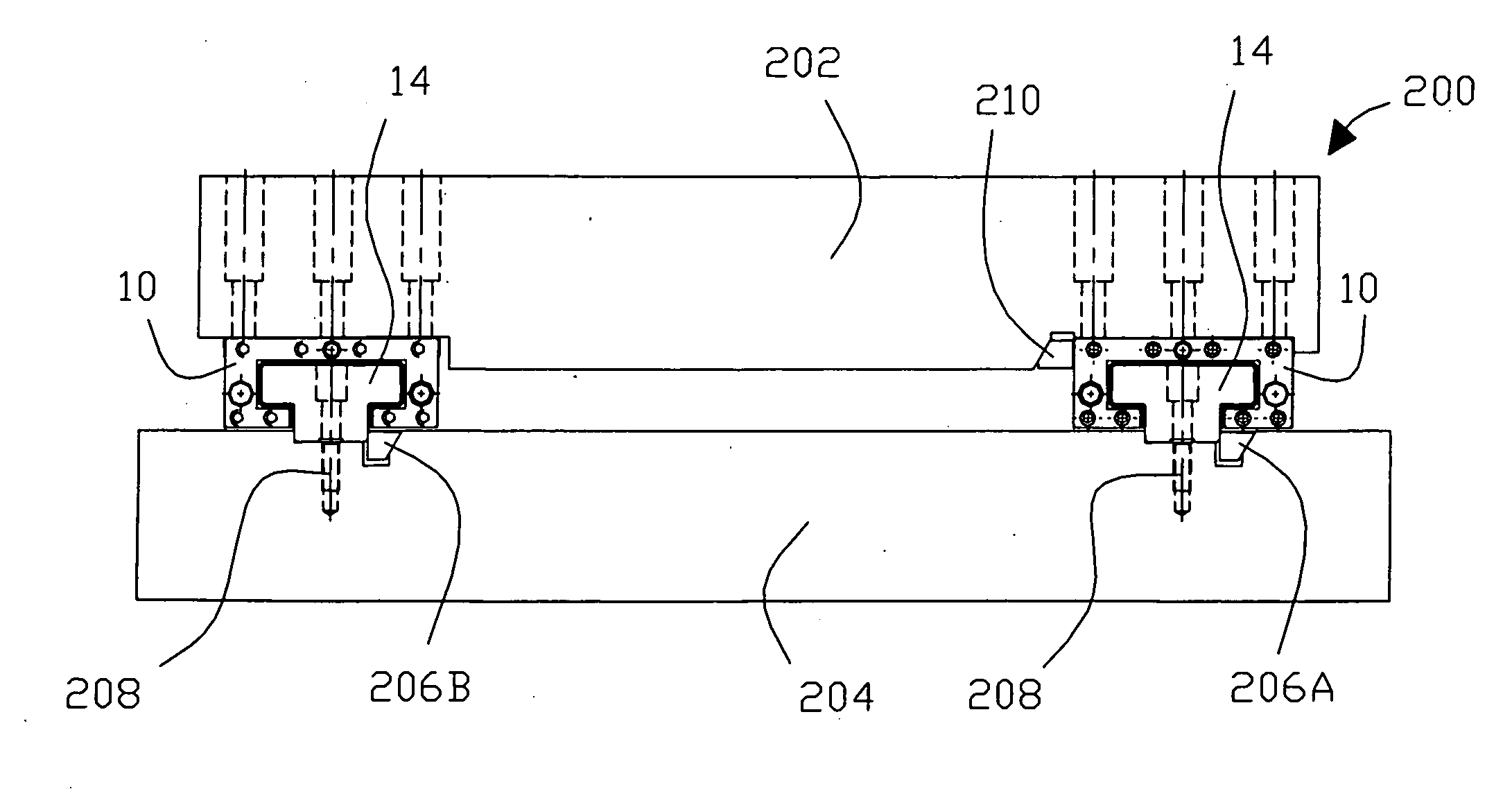
[0086] A hydrostatic bearing 10 according to the invention is installed so as to support operational movement in a QUEST® 51 turning machine (Hardinge, Inc., Elmira, N.Y., United States) using the installation procedure described above. Four hydrostatic bearings 10 according to the present invention are installed to guide motion in the X-axis and four are installed to guide motion in the Z-axis. No adaptations to the turning machine are required in order to accommodate the hydrostatic bearings 10; however, hydraulic hoses are provided for each hydrostatic bearing 10. A two-inch round A2 tool steel blank was prepared with four slots milled around its circumference for interrupted cutting. It was then hardened to 60-62 Rc. The part was then roughed with a 5 / 16 inch diameter round cubic boron nitride (CBN) insert at 450 SFM / 0.002 ipr / 0.030 doc with five passes. Subsequently, the part was finished with a 55 degree CBN insert at 550 SFM / 0.003 ipr / 0.005 doc with one pass, and then threade...


PUM


Abstract

A self-compensating hydrostatic (pressurized fluid film) linear bearing that maintains a fluid gap between a carriage and a rail when relative forces are applied. The geometric shape of the rail and mating carriage enable the bearing to have very high stiffness and load capacity without exessive detrimental carriage deformation. The carriages contain bearing grooves and lands which control and use fluid pressure to provide a very high degree of restoring force in response to changes in the fluid gap. The fluid emanating from the bearing gap is prevented from immediately leaking from the bearing carriage, and is instead routed back to the source from which it is pumped, thereby sealing the bearing carriage and simplifying the handling of the lubricating fluid. The hydrostatic bearing is particularly designed to be compact and to be bolt-for-bolt compatible with conventional linear bearings.

Description

CROSS REFERENCE TO RELATED APPLICATIONS [0001] This application is a divisional of U.S. patent application Ser. No. 10 / 617,390, filed Jul. 11, 2003, and claims priority from U.S. Provisional Patent Application No. 60 / 406,933, filed on Aug. 30, 2002, the entire contents of both of which are hereby incorporated into this application by reference.BACKGROUND OF THE INVENTION [0002] 1. Field of the Invention [0003] The invention relates to mechanical bearings and, more particularly, to hydrostatic bearings for linear motion guidance. [0004] 2. Description of Related Art [0005] A linear bearing typically includes a carriage and a rail slideably mounted on the carriage. A component, such as a moveable portion of a machine tool, is typically removably mounted on the carriage for sliding movement along the rail with the carriage. A conventional linear bearing uses rolling elements or polymer linings to reduce friction between the carriage and rail. [0006] In a hydrostatic linear bearing, lub...

Claims


Application Information

Patent Timeline
IPC IPC(8): F16C32/06F16C29/00F16C29/02F16C29/08
CPCF16C29/008F16C29/025F16C29/086F16C32/0659F16C32/0629F16C32/0644F16C29/088F16C29/02F16C29/08F16C32/06F16C33/74
Inventor WASSON, KEVIN LEESHEEHAN, TERRENCESOROKA, DANIEL
Owner MFR & TRADERS TRUST COMPANY AS AGENT
Learn More