
Axial Fan

a technology of axial fans and fans, which is applied in the direction of magnetic circuit rotating parts, piston pumps, magnetic circuit shapes/forms/construction, etc., can solve the problems of increasing heat emission from the motor itself, stators emitting heat, and consequently shortening the bearing lifespan, so as to prolong the life of stator coils and prolong the bearing lifespan. , the effect of high airflow volum

Active Publication Date: 2006-11-09
NIPPON DENSAN CORP
View PDF8 Cites 59 Cited by
  • Summary
  • Abstract
  • Description
  • Claims
  • Application Information

AI Technical Summary

Benefits of technology

[0009] In an axial fan of the present invention, inasmuch as the bearing retainer and the stator do not come into direct contact, stator-originated heat directly heating the bearing(s) is not an issue. As a result, bearing lifespan can be assured even under harsh advanced-rotating conditions in which the speed is 10,000 rpm. In implementations in which two or more bearings are retained, since the bearings together can be retained by a single bearing retainer, compared with implementations in which each bearing is retained with a different component, the coaxial precision along the bearing span is improved by at least the assemblage discrepancies that would exist between the different components. The improved precision makes it possible to reduce tilt in the journal that is inserted through the bearings, whereby vibration due to journal tilt can be kept to a minimum.
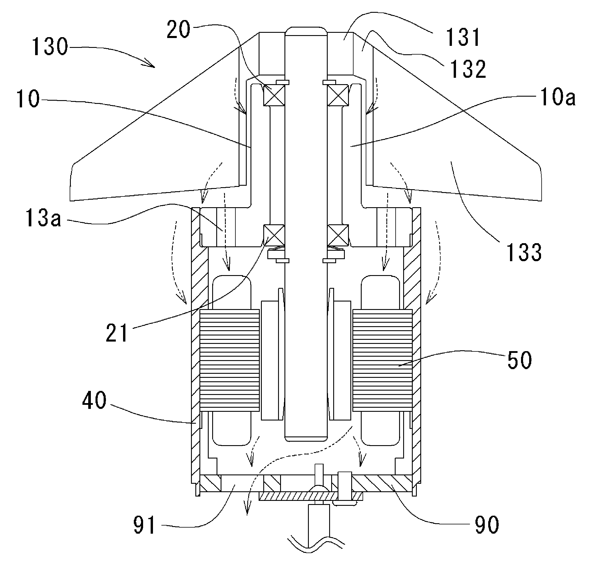
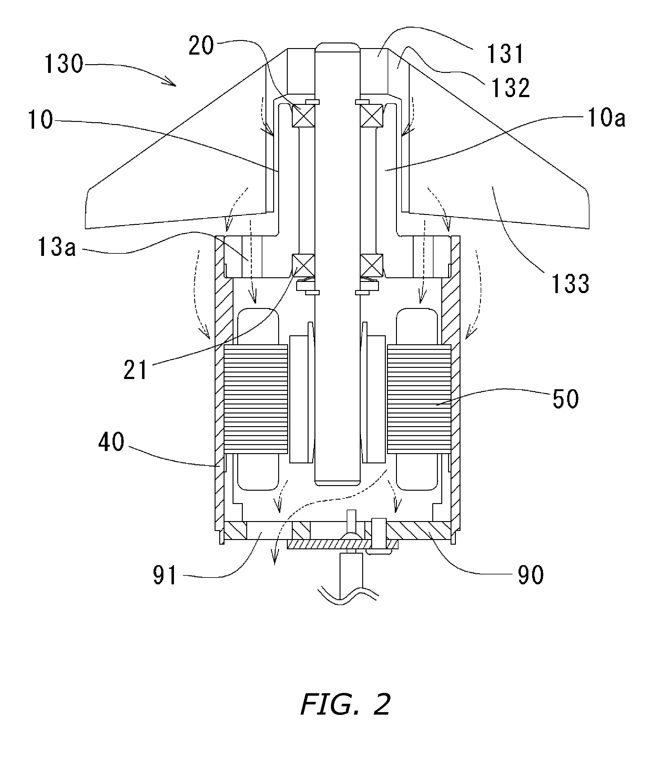
[0019] Therein, the airstream initially passes over the bearing(s) and the surfaces in proximity to the bearing retainer, and next passes over the surfaces in proximity to the stator. Given that the motor is rotated at high speed, it is necessary to supply a large current to the stator coils. The large current is, due to the coil resistance, the causative source of the emission of heat. Furthermore, with brushless motors, flowing to the stator is the high-frequency switching current that goes with running at the 10,000 rpm level, wherein an alternating magnetic field produced in the interior of the stator core by the switching current produces hysteresis loss that is given off as heat. Consequently, in the motor during high-speed rotation, initially the stator heats up. A further consequence, meanwhile, is that during the high-speed rotation the bearing(s) continually undergo impact, which becomes heat produced in the bearing(s). In the present invention, the airstream produced by the fan impeller initially cools the bearing(s) and the bearing retainer, and next cools the stator, which has become the most heated. This enables the bearing(s) to be air-cooled efficaciously, in turn making it possible to prolong the bearing lifespan. Moreover, the airstream enables the stator, having risen to a high temperature, to be air-cooled at the same time, making it possible to prolong the lifespan of the stator coils. These features enable the realization of a high-airflow-volume, long-lifespan fan motor optimal for sever computers and other devices that are operated continuously over the long term without pause.

Problems solved by technology

Nevertheless, improving the motor revs entails the problem of heat emission from the motor itself increasing.
That is, the goal of raising the revs in a motor gives rise to the necessity of passing greater current to the motor's stator, and this turns out to cause the stator to emit heat.
On that account, the bearing unit is subjected, more than is necessary, to the influences of the heat produced by the stator, which has led to the problem of the bearing lifespan consequently being shortened.
Moreover, the bearing unit is continually subjected to strong rotational impact due to the increase in motor revs.
The rotational impact causes the bearing(s) itself to emit heat, shortening the bearing lifespan all the more.
In that raising the motor revs also makes the motor's magnetic-pole switching more frequent, the vibrations produced when the magnetic poles are switching turn out be a serious problem.

Method used


Image

  • Axial Fan
  • Axial Fan
  • Axial Fan

Examples


Embodiment Construction

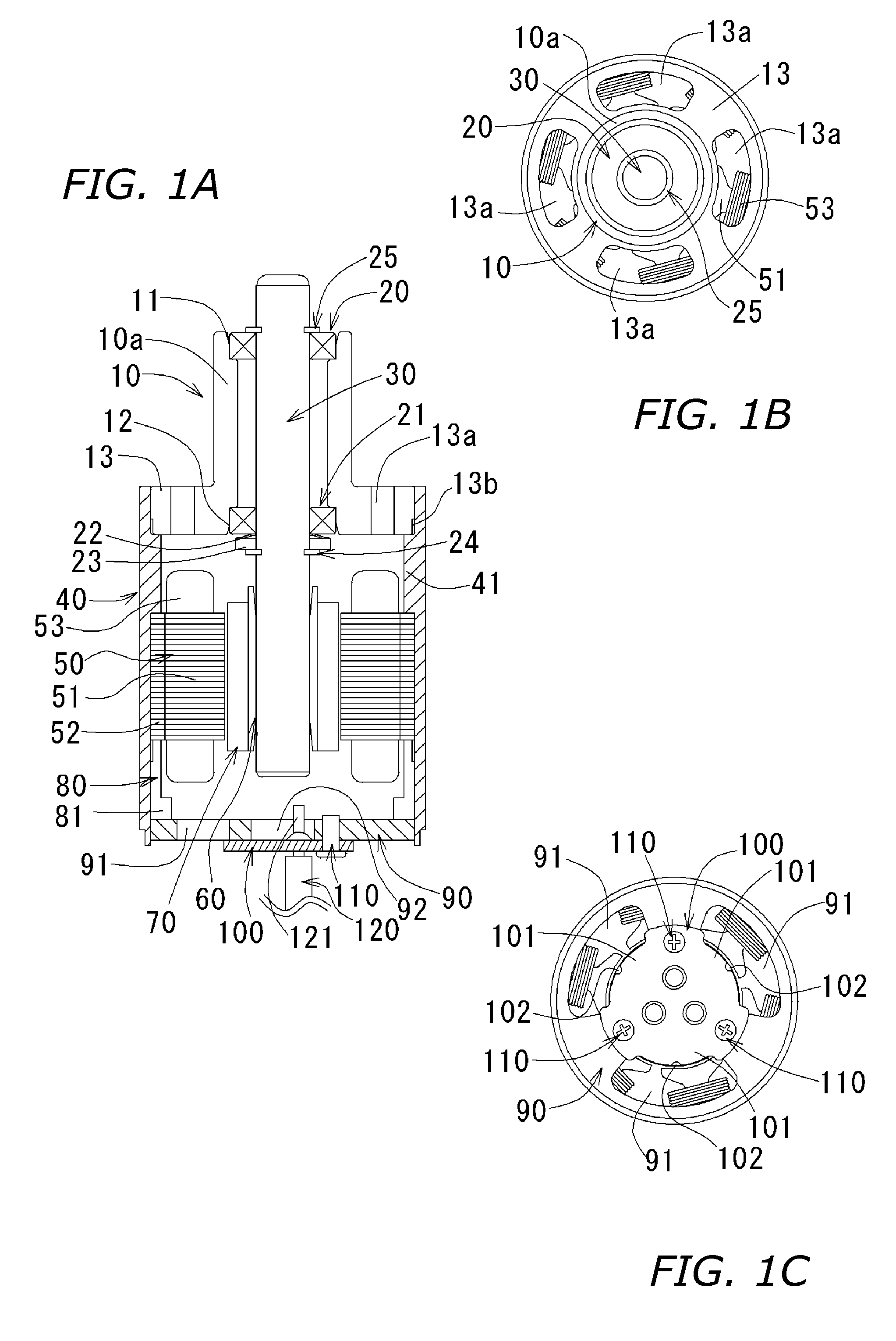
[0023]FIGS. 1A to 1C illustrate one embodiment of a brushless motor according to the present invention. Throughout the specification, the up / down directions are defined using the up / down orientations along the shaft axis in FIG. 1A. Accordingly, FIG. 1A presents a schematic sectional view of the motor taken along the shaft axis, FIG. 1B, an upper-side view, and FIG. 1C, an underside view.

[0024] A bearing retainer 10 in FIG. 1A is made of die-cast aluminum, and is rendered in a hollow cylindroid form. The bearing retainer 10 has a bearing-retaining cylinder 10a for retaining later-described bearings. The bearing-retaining cylinder 10a has respective recesses 11 and 12 at the upper and lower ends of the bearing-retaining cylinder 10a. These recesses 11 and 12 are die-cast and thereafter machine-processed to enhance the coaxial precision. These recesses 11 and 12 accommodate respective ball bearings 20 and 21, which are press-fit into the recesses. The present structure enables the ba...


PUM


Abstract

In an axial fan, a case (40) accommodating the fan motor stator (50) is anchored into a bearing retainer (10), in which ball bearings (20, 21) as a bearing unit are accommodated, along a bulge part (13) formed on the lower end portion thereof. The case (40) extends heading axially downward, wherein there is no diametrical overlap between the ball bearings (20, 21) and the stator (50). Since only the bulge part (13) of the bearing retainer (10) is fixed to the case (40), heat arising from the stator (50) is thermally conveyed via the case (40) only to the bulge part (13). The fact that the thermal conveyance zone is minimal enables unrestrained curtailment of heat transmitted to the ball bearings (20, 21). As a result the axial fan can be designed for prolonged bearing lifespan.

Description

BACKGROUND OF THE INVENTION [0001] 1. Technical Field [0002] The present invention relates to axial fans (given simply to be “motors” hereinafter), in particular to axial-fan motor structures involving 10,000 rpm and faster high-speed rotation. [0003] 2. Description of the Related Art [0004] Owing to improvements in the processing speed of integrated circuits employed in server computers, the amount of heat emission from servers themselves has been on the rise in recent years. Thus, securing the airflow volume necessary in order stably to cool server-computer integrated circuits has become a critical requirement demanded of server-cooling fan motors. Consequently, there has been an urgently felt need to improve the revs of fan motors. [0005] Nevertheless, improving the motor revs entails the problem of heat emission from the motor itself increasing. That is, the goal of raising the revs in a motor gives rise to the necessity of passing greater current to the motor's stator, and this...

Claims


Application Information

Patent Timeline
Patent Type & Authority Applications(United States)
IPC IPC(8): H02K9/00H02K5/16F04B17/00
CPCF04D25/082H02K9/06H02K5/1735H02K1/185H02K5/225F04D29/5806
Inventor YAMAMOTO, MASATO
Owner NIPPON DENSAN CORP
Learn More