[0007] In conventional custom paint procedures, intricate designs having remarkable color effects are achieved only by applying paint by hand or
spray painting with repeated hand applied masking techniques. It was previously thought that color effects could only be achieved through the laborious process of hand application of a large number of paints and clear-coats directly to the article to be painted. As a result, a cottage industry of specialized paint shops has developed, with custom paint artisans establishing a world-wide reputation for the color effects that they can achieve through their
highly skilled work. Surprisingly, using printing processes capable of
mass production, highly detailed images can be prepared in accordance with the present invention that have the appearance of images that heretofore could only be applied directly to a substrate, such as a motorcycle or automobile, through laborious custom paint procedures.
[0008] The present invention provides unique image graphic delivery for high quality images to achieve color effects not heretofore realizable. In one aspect of the present invention, a transferable image for water-slidable application to surfaces is provided comprising a water-absorbing Porous Backing Sheet that has been coated with a water-soluble
Resin Coating. A plurality of ink
layers is located on the water-soluble Resin
Coating, at least one of the ink layers being translucent or transparent and applied in overlapping fashion in a manner to provide a
color effect.
[0009] For purposes of the present invention, a “
color effect” is defined as the
visual impression afforded to the viewer by observing an interaction between two or more overlapping layers of ink. The interaction may be manifested in the appearance of depth, flop, shimmer, pearlescence, metallic effect, shadowing effect, color change based on
angle of view and / or ambient
light intensity, and flashy looks colloquially termed as “bling-bling,” or other such optical effects as will now be apparent to the skilled artisan. The final graphic image provides the appearance of custom paint details, with the
advantage of the capability to
mass produce the desired image and apply the image at any location, such as factory settings or in custom automobile or motorcycle shops.
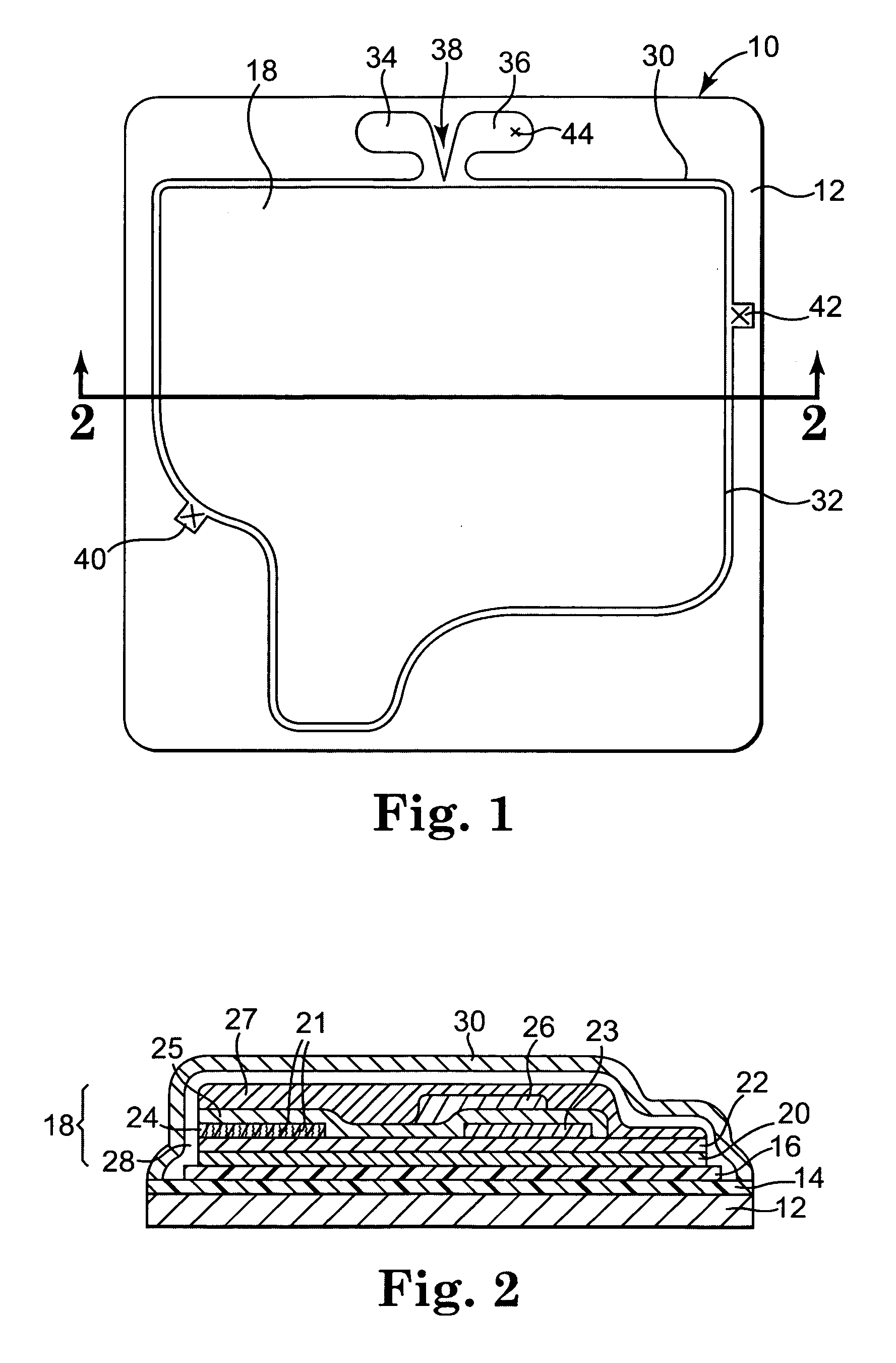
[0010] In another aspect of the present invention, transferable images for water-slidable application to surfaces are provided having exceptional ease and precision in transfer are provided. In this aspect, a transferable image construction is provided wherein a water-absorbing Porous Backing Sheet is coated with a water-soluble Resin
Coating. At least one ink layer is provided on the water-soluble Resin
Coating, and a transparent top layer is additionally provided that completely overcoats the ink layer and defines an image shape having a perimeter. Finally, a transfer premask is provided that completely overcoats the transparent top layer, wherein the transfer premask is substantially no wider than about 0.25 inches than the transparent top layer at the perimeter of the image shape. This
image transfer construction comprising the transfer premask provides an image that can be readily transferred to a target substrate with precision and with
high integrity of the image. The transfer premask provides stability to the image for effective transfer. Because the transfer premask is substantially not more than about 0.25 inches wider than the transparent top layer at the perimeter of the image shape, the water that is carried with the image during transfer can be efficiently and substantially removed by careful squeegee techniques without damaging the image. Additional optional features can be provided to assist or enhance ease of placement of the transferable image to a target substrate in an easy to use
system. Examples of such features include incorporating transfer premask perimeter structures configured to propagate a tear upon removal from the transferable image, tab structures to assist in removal of the transfer premask from the transferable image, locator markers to assist in accurate placement of the transferable image to a target substrate, and combinations thereof.
[0011] In addition to advantages discussed above, the present transferable
image system provides unique advantages. In one aspect, the final image on the substrate is superior to that which can be achieved by merely printing an image on top of a conventional
adhesive coated
polymer base film (such as a vinyl film), because the thickness of the
adhesive coated
polymer films introduces deformities in the image that are readily visible to the discerning viewer. Additionally, conventional vinyl base films that are often used for providing a transferable image to a target substrate have typical thicknesses of at least about 2 mils, and often 4 mils, before the image is printed on the vinyl, and additionally comprise a
pressure sensitive adhesive layer that is 1 mil thick. Such vinyl films present a very noticeable and an objectionable edge due to the 3 to 5 mil or greater profile of the product that is adhered to the target substrate. In contrast, the image of the present invention when in place on the target substrate preferably has a
total thickness (i.e. including top and base layers, if present, and all ink layers) of less than about 2 mils, more preferably a
total thickness of less than about 1.5 mils. Particularly preferred embodiments of the present invention have a
total thickness of less than about 0.8 mils, and more preferably a total thickness of less than about 0.5 mils.
[0013] The present transferable
image system additionally provides readily shippable detailed, high quality images that can be easily applied to any substrate on location if desired. For example the images as described herein can be designed for application to signboard or backlit sign substrates and cheaply shipped to distant locations for application to commodity stock material closer to the location of
actual use, thereby substantially reducing shipping costs.
