
Electronically scanned wideband antenna

a wideband antenna and electromagnetic scanning technology, applied in the direction of slot antennas, antennas, instruments, etc., can solve the problems of preventing especially the obtaining of precise images, deflection of the antenna beam, and inability to compensate for the deflection due to the frequency variation in the control of the phase shifter, etc., to achieve the effect of compact antenna

Inactive Publication Date: 2006-11-02
THALES SA
View PDF8 Cites 9 Cited by
  • Summary
  • Abstract
  • Description
  • Claims
  • Application Information

AI Technical Summary

Benefits of technology

[0012] The main advantages of the invention are that it can makes it possible to obtain a compact antenna, can be used in numerous applications and is economical.

Problems solved by technology

However, for this same state of the phase-shifters, when the sending frequency varies, there is a deflection of the antenna beam.
The use of standard electronically scanned antennas prompts a dispersal of antenna aiming with respect to frequency variations as in a sprinkling or scattering process, thus preventing especially the obtaining of precise images.
These deflections due to the frequency variations cannot be compensated for in the control of the phase-shifters because their maximum phase shift is limited to 360°.
However, such an approach particularly complicates the structure of the antennas:it increases their weight and also their cost.

Method used


Image

  • Electronically scanned wideband antenna
  • Electronically scanned wideband antenna
  • Electronically scanned wideband antenna

Examples


Embodiment Construction

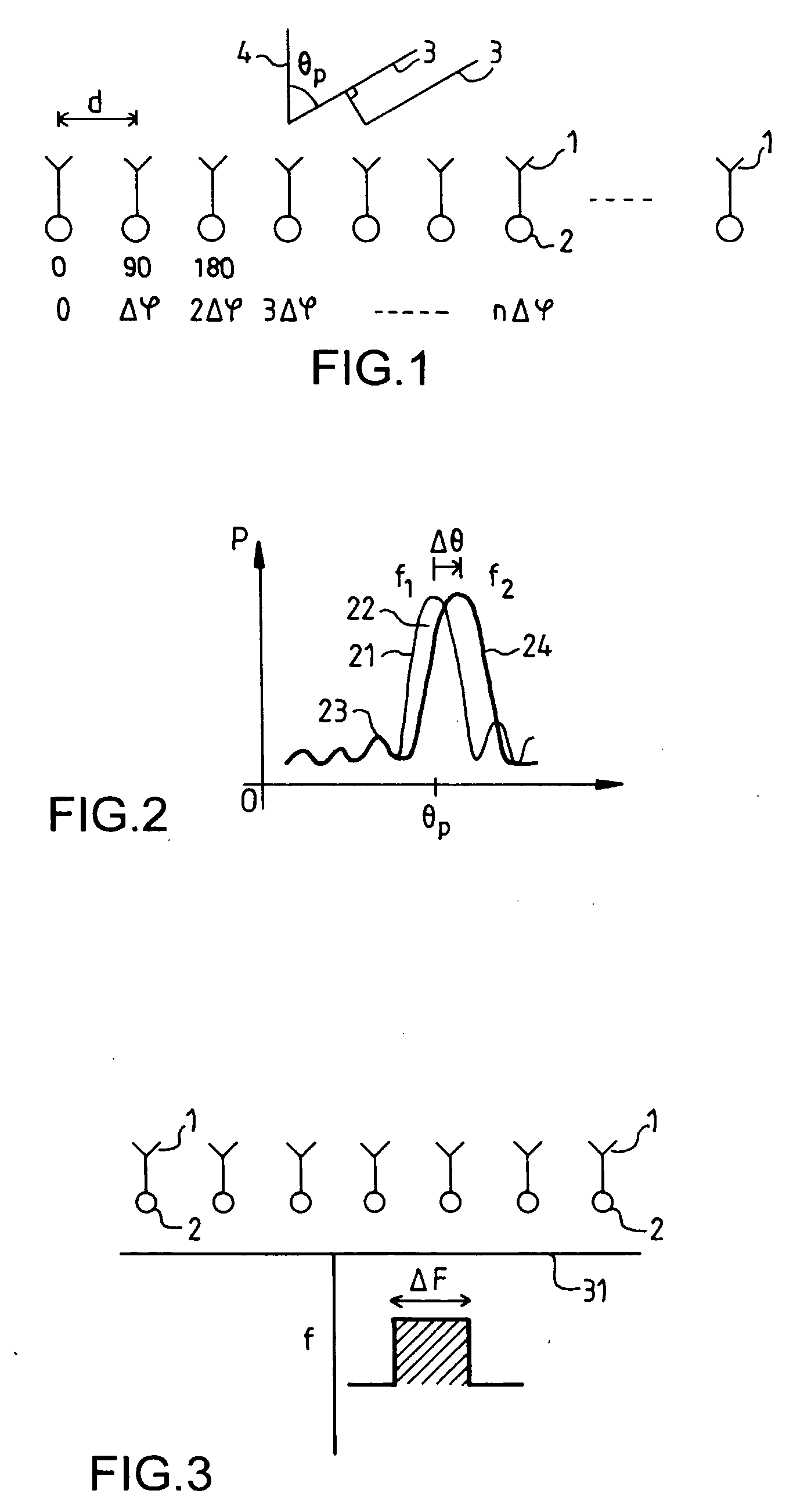
[0021]FIG. 1 recalls the principle of operation of an electronically scanned antenna. The antenna has an array of microwave sources 1 or radiating elements. Each element 1 is connected to a phase-shifter 2. At emission, the microwave signals designed to be sent by the sources are first of all phase-shifted by the phase-shifters 2 to according to a well-established law that defines the aiming direction 3 of the antenna beam. This direction 3 is defined by an aiming angle θp relative to the axis 4 of the antenna, this direction 4 being perpendicular to the plane of the antenna. The array shown in FIG. 1 is linear, but it also represents a plane array where each source actually represents an element of a line of the array where all the sources of this line have the same phase shift.

[0022] It is also possible to apply a zero phase shift or a reference phase shift to the first line, represented by the first source of the array of FIG. 1. Then, the phase is incremented by one phase shift...


PUM


Abstract

An electronically scanned antenna working in a wide frequency band comprises at least: one reflector panel comprising an array of phase-shifters cells; one slotted waveguide illuminating the reflector panel by a microwave having a variable frequency f. The deviation Δθf of the direction of the wave emitted by the slotted waveguide, as a function of the frequency variations, countering the variation Δθp of the aiming direction of the wave reflected by the reflector panel. The disclosed antenna can be used especially in applications requiring compact or low-cost antennas.

Description

BACKGROUND OF THE INVENTION [0001] The present invention relates to an electronically scanned antenna working in a wide frequency band. It can be used especially in applications requiring compact or a low-cost antennas. [0002] An electronically scanned antenna comprises a network of microwave sources associated with a phase-shifter. It is known that the direction of the antenna beam depends on the phase shifts applied by the phase-shifters to the source signals. For a given state of the phase-shifters and a given frequency, a well-defined direction of antenna beam is obtained. However, for this same state of the phase-shifters, when the sending frequency varies, there is a deflection of the antenna beam. There are many applications that require the instantaneous sending of a frequency band of varying width. This is the case especially with SAR (Synthetic Aperture Radar) type radar imaging applications. Such applications work, for example, in instantaneous bands in the range of sever...

Claims


Application Information

Patent Timeline
IPC IPC(8): H01Q13/10
CPCG01S13/90H01Q19/195H01Q3/46H01Q3/22
Inventor CHEKROUN, CLAUDE
Owner THALES SA
Learn More