
Numerical controller

a controller and number technology, applied in the field of numerical controllers, can solve the problems of waste of machining cycle, high processing cost, and corresponding delay in operation of the controller, and achieve the effect of reducing the cost of machining cycle, saving time and money

Active Publication Date: 2006-10-26
FANUC LTD
View PDF9 Cites 15 Cited by
  • Summary
  • Abstract
  • Description
  • Claims
  • Application Information

AI Technical Summary

Benefits of technology

The present invention provides a numerical controller that can perform an auxiliary function at a specific time or position of a spindle, even when an override is applied. The controller stores time or spindle position data as a table, along with information about the operation delay time for each auxiliary function command. The controller then outputs the auxiliary function commands at the designated time, with the operation delay time added in. This allows the auxiliary function to be performed without any delay at the commanded reference position, even when an override is entered.

Problems solved by technology

Since the actual auxiliary function is subject to an operation delay, however, its operation is correspondingly delayed behind its output.
Thus, data must be prepared taking account of the actual override value, so that the data adjustment takes a lot of time, and the machining cycle is wasteful.

Method used


Image

  • Numerical controller
  • Numerical controller
  • Numerical controller

Examples


Embodiment Construction

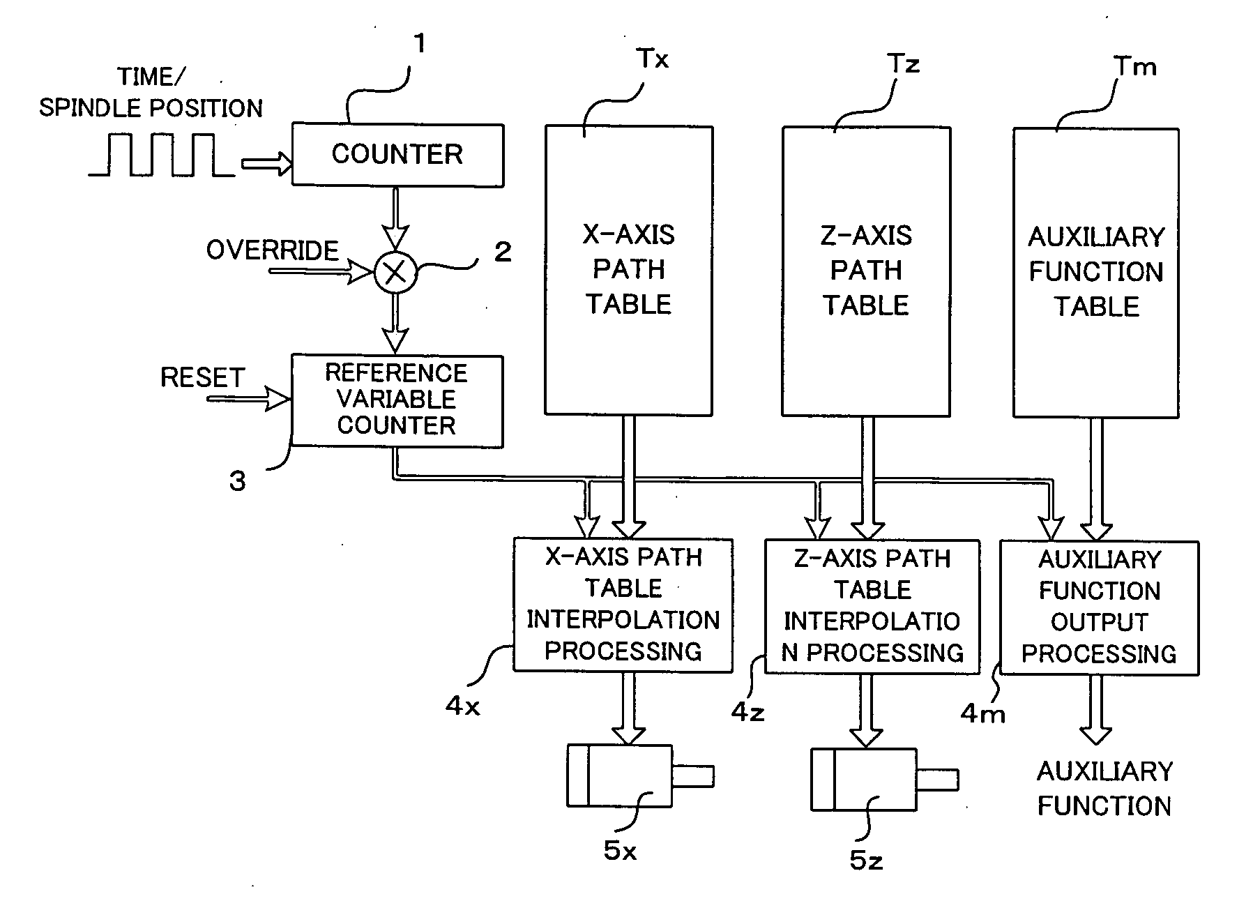
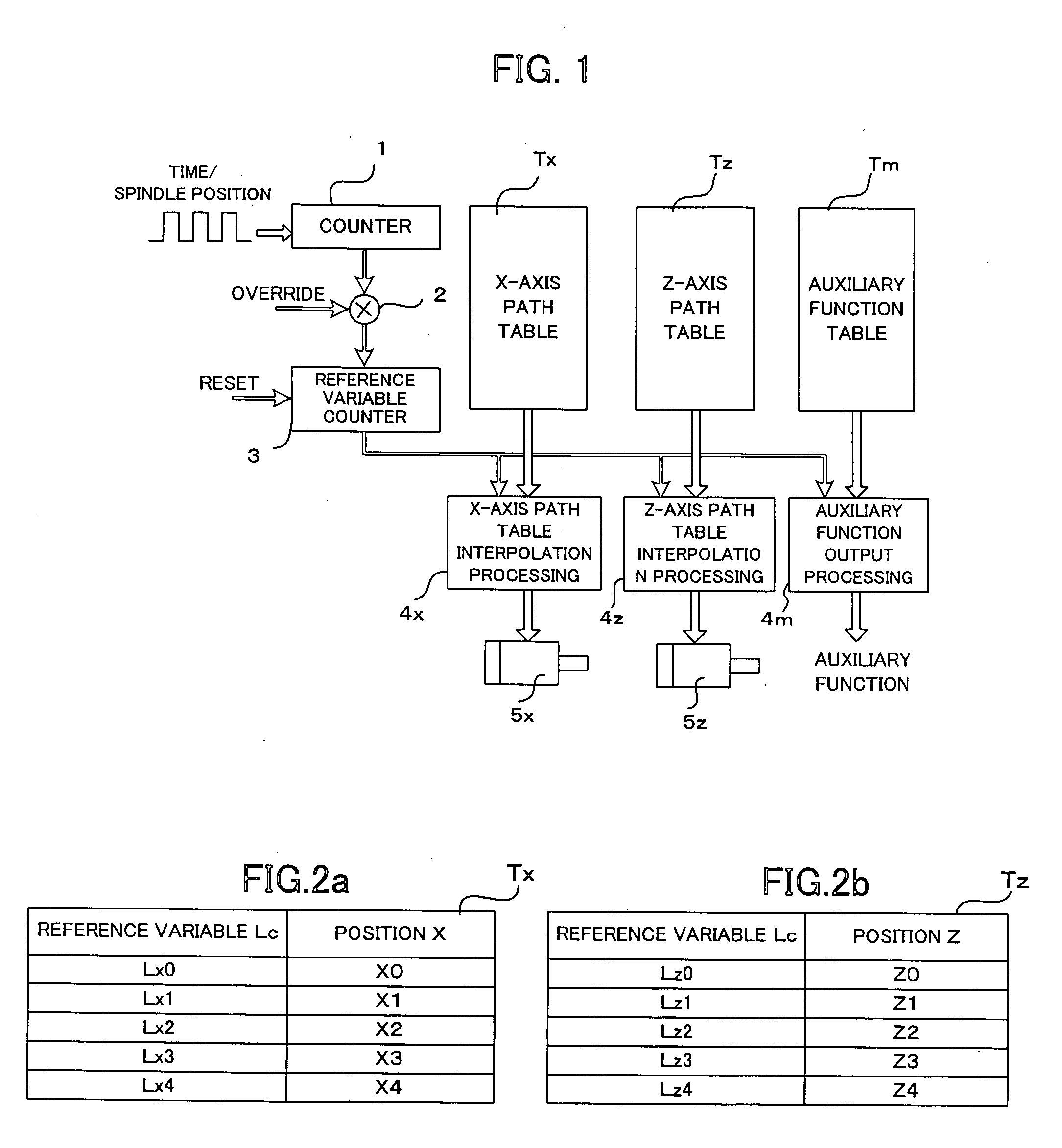
[0022]FIG. 1 is a schematic diagram showing path table operation functions executed by one embodiment of the present invention. In FIG. 1, pulses that indicate spindle positions from a position coder mounted on a spindle or reference pulses based on time from an external pulse generator section are inputted to a counter 1 and counted for each given period. Alternatively, the spindle positions may be counted in accordance with a command value for the spindle. For the reference pulses that are based on time, a count value in the counter 1 is multiplied by a scale factor set in override means by a multiplier 2 and stored in a reference variable counter 3. If the spindle positions are used as references, the override value is 100%. The reference variable counter 3 is reset when the path table operation functions are commanded, and path table operation is performed based on values L in the reference variable counter 3.

[0023] The values L in the reference variable counter 3 are inputted ...


PUM


Abstract

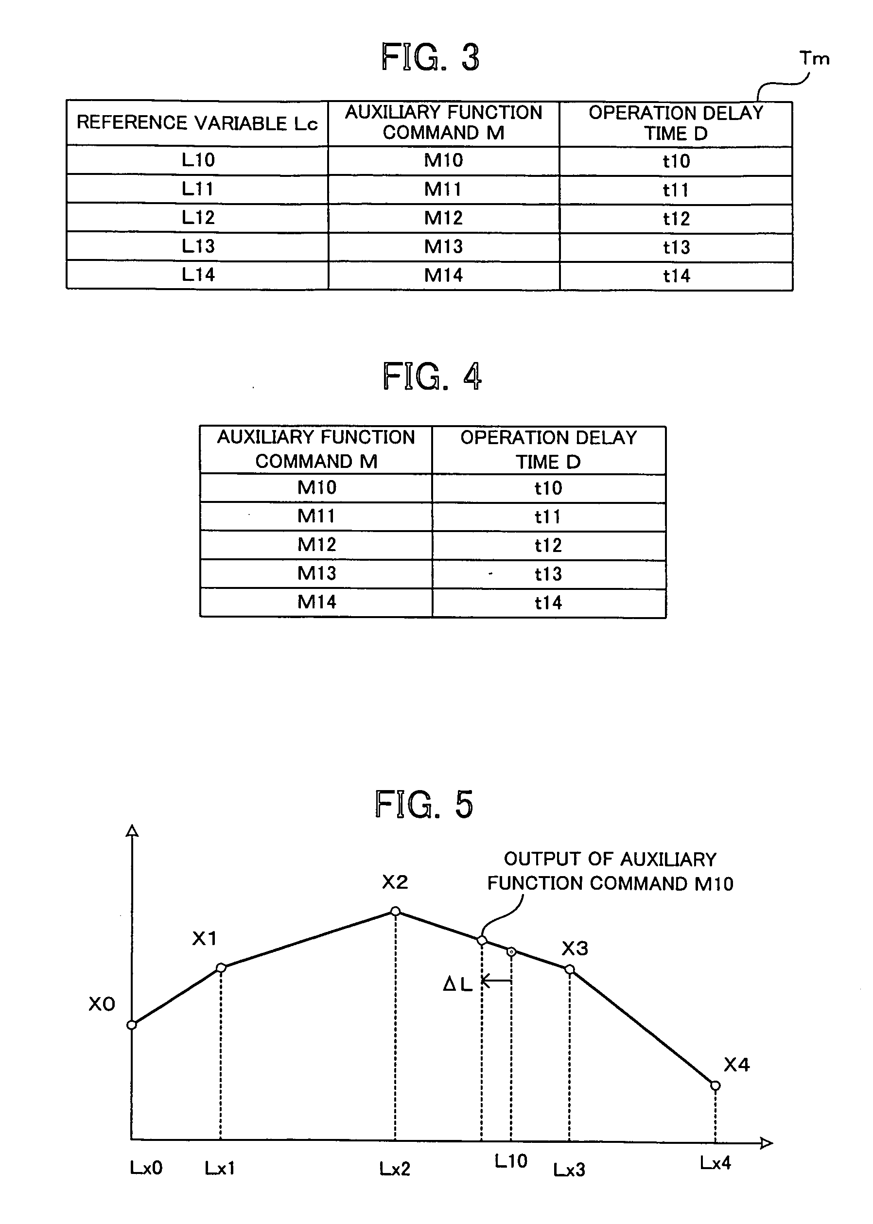
A numerical controller capable of operating an auxiliary function at a target time or spindle position in performing operation based on table format data. An auxiliary function table is stored with auxiliary function commands M to be outputted corresponding to commanded reference times Lc and their corresponding operation delay times D. A reference time L is updated based in accordance with an override value. An auxiliary function command M and its corresponding operation delay time D are read from the auxiliary function table. The delay time D is corrected with the override value, and a reference time prior to a commanded reference time Lc by a margin equivalent to the corrected delay time is set as a command time Lr. If an override is entered, the delay time is corrected for the override amount and modified into an overridden reference time unit, and a command time for an auxiliary function is obtained and outputted based on the reference time unit. Thus, the auxiliary function is performed appropriately at a commanded value Lc of the reference time.

Description

BACKGROUND OF THE INVENTION [0001] 1. Field of the Invention [0002] The present invention relates to a numerical controller for controlling a machine tool, and more particularly to a numerical controller for drivingly controlling respective axes in accordance with data stored in the form of a table. [0003] 2. Description of Related Art [0004] Conventionally known is a numerical controller in which motion amounts and positions of individual axes are previously stored in a table format, and the axes are drivingly controlled based on the data stored in the table, not on block commands from an NC program. Thus, according to this arrangement, a tool can be freely operated without being restricted by the conventional block commands, so that the machining time is shortened and the machining accuracy is enhanced. [0005] According to a well-known invention (see JP 59-177604A), a position of a movable axis for each time or rotation angle, for example, is previously stored as numerical control...

Claims


Application Information

Patent Timeline
Patent Type & Authority Applications(United States)
IPC IPC(8): H04L27/06H03D1/00G05B19/18
CPCG05B19/414G05B2219/41206G05B2219/50233G05B2219/50218G05B2219/43093
Inventor ENDO, TAKAHIKOTAKEUCHI, YASUSHI
Owner FANUC LTD
Learn More