
Desktop charger for a portable electronic device with a display

a portable electronic device and display technology, applied in the field of portable wireless communication device charging devices, can solve the problems of inability to predict additional factors, inability to match the unique needs of a particular user, and inability to meet the tilt angle set by the manufacturer, so as to reduce the cost of manufacture and assembly, and facilitate transportation while travelling

Inactive Publication Date: 2006-10-26
KYOCERA CORP
View PDF6 Cites 18 Cited by
  • Summary
  • Abstract
  • Description
  • Claims
  • Application Information

AI Technical Summary

Benefits of technology

[0005] According to various embodiments of the invention, one or more of the following benefits may be realized by the variable position desktop charger including, for example, a user can tailor the position of the phone display to his own size, seating position, room lighting, or any other condition that might make it desirable to reposition one's phone. In other embodiments, the variable position desktop charger may be collapsible, providing the additional benefit of being easy to transport while travelling. Finally, in some embodiments the invention may be simplified such that the cost of manufacture and assembly are reduced.

Problems solved by technology

However, since mobile phone users come in a continuous variety of sizes, the preset tilt angles set by the manufacturer may not match the unique needs of a particular user.
Moreover, there exist additional factors that are continuous in nature and cannot be predicted.
For example, the particular lighting of a room may cause glare on the phone display at unanticipated angles, the sun's travel may cause glare, or the user might seek to position the display in a “sweet spot” according to his or her sitting position or even mood.

Method used


Image

  • Desktop charger for a portable electronic device with a display
  • Desktop charger for a portable electronic device with a display
  • Desktop charger for a portable electronic device with a display

Examples


Embodiment Construction

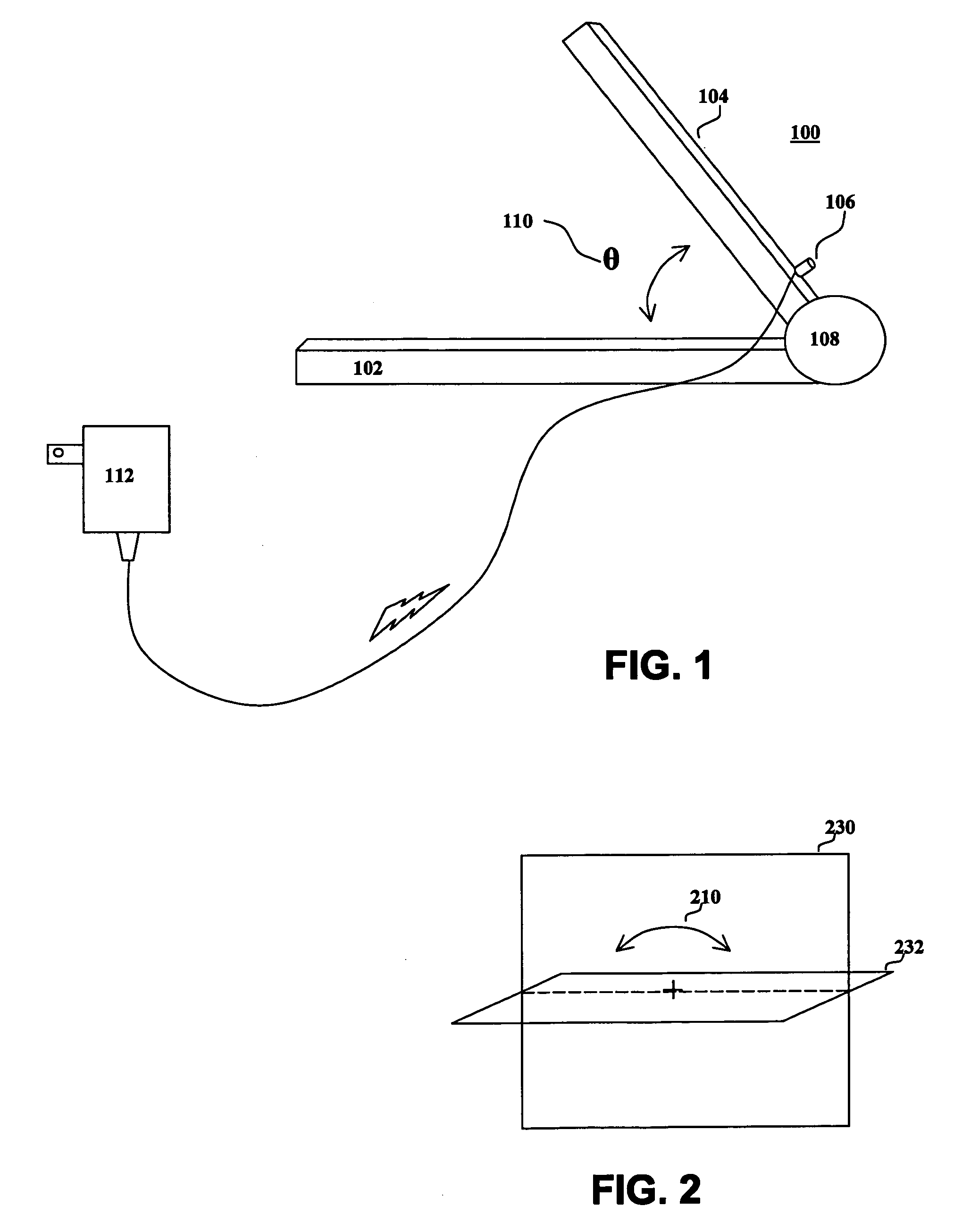
[0015] Referring first to FIG. 1, there is shown a simplified block diagram of exemplary variable position desktop charger 100 for a portable electronic device (not shown) according to one embodiment of the present invention. Variable position desktop charger 100 comprises base 102, cradle 104, electrical interface 106, and battery charger 112.

[0016] Base 102 supports the remainder of the structure on a substantially horizontal surface such as a desktop. However, base 102 is not limited to this function alone. For example, base 102 may also include a storage area. The storage area may store an additional portable electronic device battery or batteries. The storage area might also store a DC charging source, an AC adapter, an accessory to the portable electronic device, etc.

[0017] In certain embodiments, base 102 may also contain circuitry such as an additional charge circuit for charging additional batteries, a charge protection circuit to prevent overcharging, a charging priority...


PUM


Abstract

An exemplary variable position desktop charger comprises a base, a cradle, an electrical interface, and a charger. The base and cradle are rotatably coupled such that the display of the portable electronic device can be adjusted continuously between a first angle and a second angle.

Description

FIELD OF THE INVENTION [0001] The present invention relates to portable electronic devices. More specifically, the invention relates to charging devices for portable wireless communication devices. BACKGROUND OF THE INVENTION [0002] Desktop mobile phone chargers are currently known for charging a mobile phone battery situated in a cradle. US Pat. App. No. 2005 / 0024011 discloses a mobile phone charger in which a mobile phone is held upright by the charger, which then rests on a surface, such as a desktop. Additionally, there currently exist charging devices that provide for positioning the phone at various preset positions. US Pat. App. No. 2004 / 0204056 discloses a mobile phone charger in which the phone is held in position by a thumb-release latch mechanism that allows a user to position the tilt of the phone at the nearest fixed angle groove. [0003] However, since mobile phone users come in a continuous variety of sizes, the preset tilt angles set by the manufacturer may not match ...

Claims


Application Information

Patent Timeline
IPC IPC(8): H02J7/00
CPCH04M1/04H02J7/0044
Inventor ROSAL, KIMSACHDEVA, SUZANKNISH, GEORGE
Owner KYOCERA CORP
Learn More