
Plasma-assisted processing in a manufacturing line

Inactive Publication Date: 2006-10-26
DANA CORP
View PDF99 Cites 9 Cited by
  • Summary
  • Abstract
  • Description
  • Claims
  • Application Information

AI Technical Summary

Benefits of technology

[0008] An apparatus for plasma-assisted processing a plurality of work pieces according to the present invention can include a first chamber, the first chamber coupled to receive a gas flow and radiation in order to ignite a first plasma within the first chamber; a second chamber, the second chamber coupled to receive a gas flow and radiation in order to ignite a second plasma within the second

Problems solved by technology

However, igniting, modulating, and sustaining plasmas for these purposes can be difficult for a number of reasons.
However, radiation sources capable of supplying such large intensities can have several disadvantages; they can be expensive, heavy, bulky, and energy-consuming.
Moreover, these large radiation sources normally require large electrical power supplies, which can have similar disadvantages.
However, vacuum equipment, which can be used to reduce this pressure, can limit manufacturing flexibility, especially as the plasma chambers become large and especially in the context of manufacturing lines.
Such a device, however, only sparks periodically and therefore can only ignite a plasma periodically, sometimes causing an ignition lag.
Moreover, conventional sparking devices are normally powered with electrical energy, limiting their use and position in many manufacturing environments.

Method used


Image

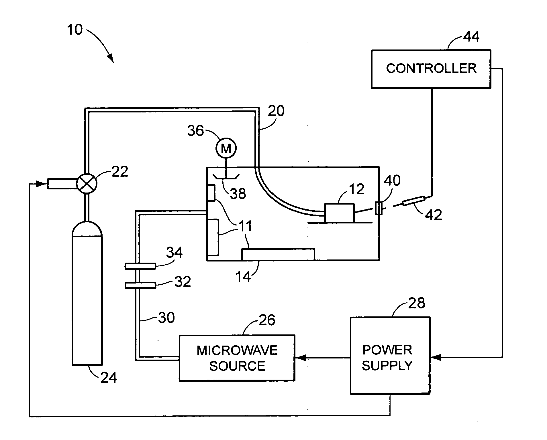
  • Plasma-assisted processing in a manufacturing line
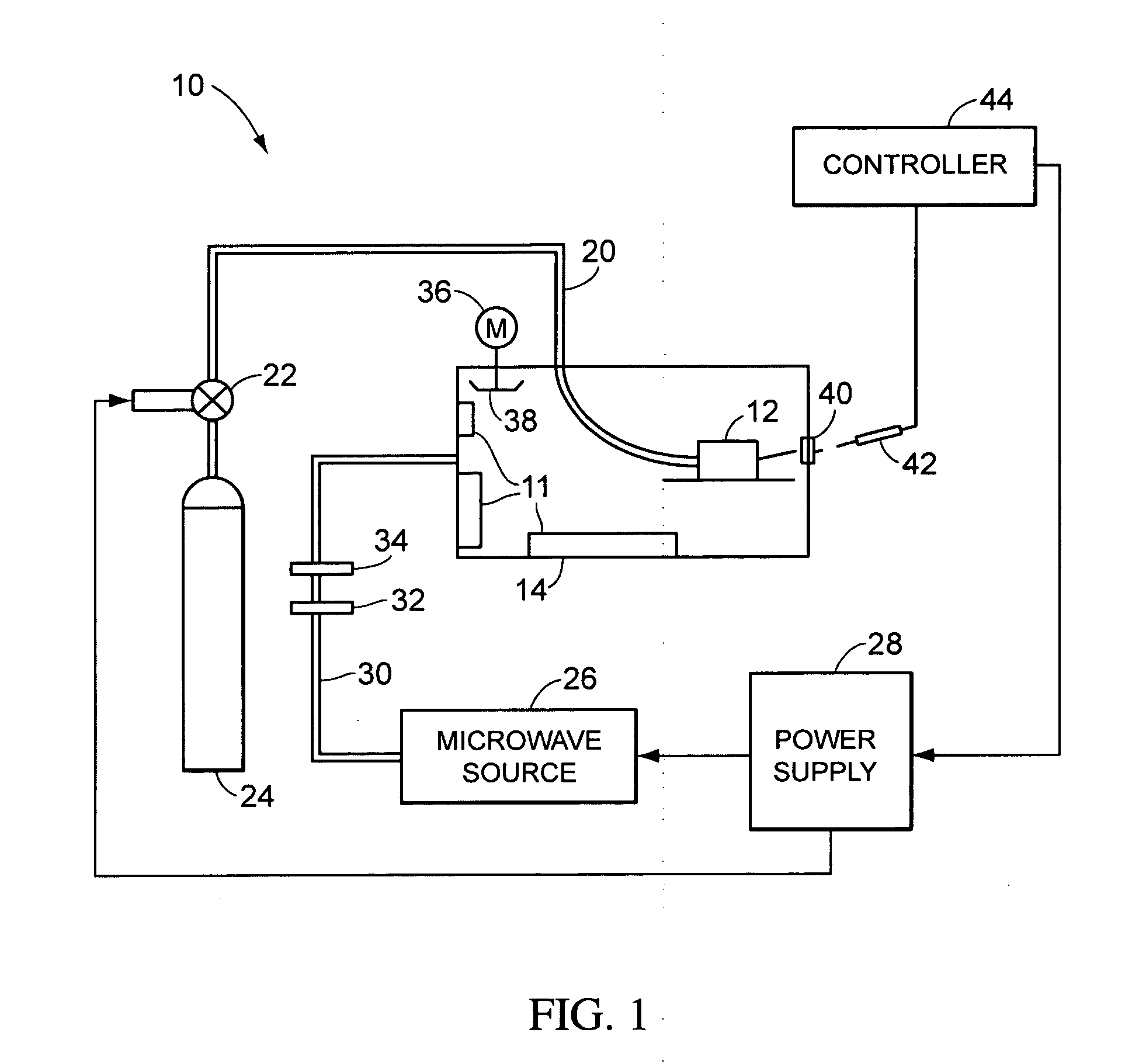
  • Plasma-assisted processing in a manufacturing line
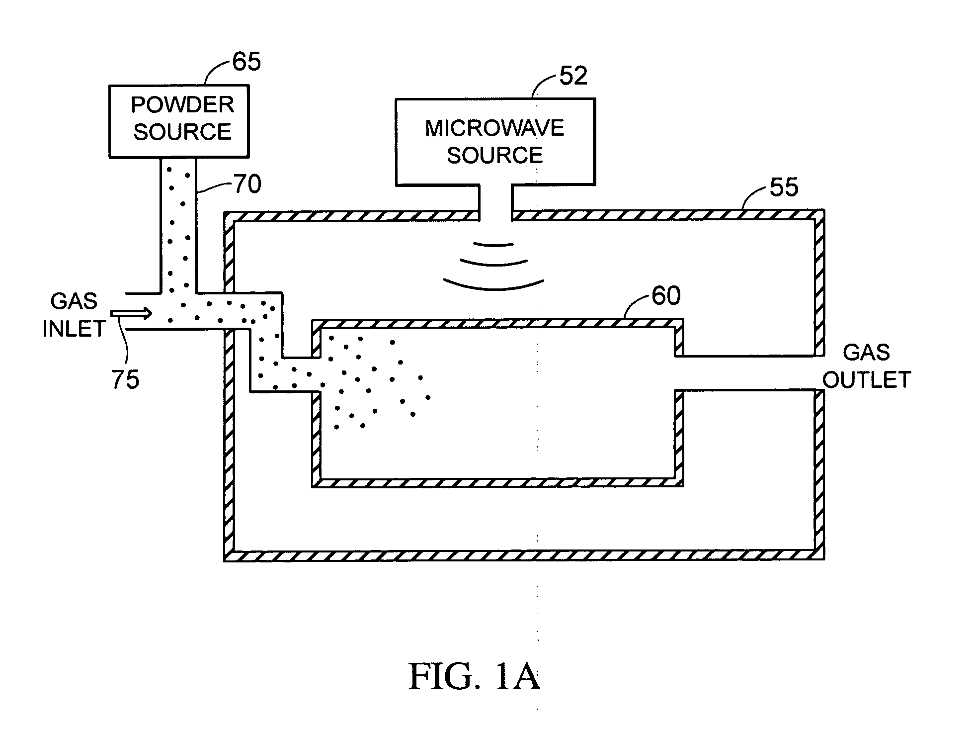
  • Plasma-assisted processing in a manufacturing line

Examples


Embodiment Construction

[0036] This invention relates to methods and apparatus for plasma-assisted processing in a manufacturing line and can be used to lower energy costs and increase manufacturing flexibility.

[0037] The following commonly owned, concurrently filed U.S. patent applications are hereby incorporated by reference in their entireties: Kumar et al. U.S. patent application Ser. No. 10 / 513,221 (Atty. Docket No. 1837.0008), U.S. patent application Ser. No. 10 / 513,393 (Atty. Docket No. 1837.0009), PCT Application PCT / US03 / 14132 (Atty. Docket No. 1837.0010, now abandoned), U.S. patent application Ser. No. 10 / 513,394 (Atty. Docket No. 1837.0011), U.S. patent application Ser. No. 10 / 513,305 (Atty. Docket No. 1837.0012), U.S. patent application Ser. No. 10 / 513,607 (Atty. Docket No. 1837.0013), U.S. Pat. No. 6,870,124 (Atty. Docket No. 1837.0015), PCT Application No. PCT / US03 / 14034 (Atty. Docket No. 1837.0016, now abandoned), U.S. patent application Ser. No. 10 / 430,416 (Atty. Docket No. 1837.0017), U.S...


PUM

PropertyMeasurementUnit
Electrical conductivityaaaaaaaaaa
Electrical conductoraaaaaaaaaa
Areaaaaaaaaaaa

Abstract

Methods and apparatus are provided for plasma-assisted processing multiple work pieces in a manufacturing line. The manufacturing line can include a plurality of microwave cavities, each of the microwave cavities igniting and sustaining a microwave plasma. Work pieces can be shuttled between the plurality of microwave cavities on a conveyance system that controls the positioning of each of the work pieces.

Description

CROSS-REFERENCE OF RELATED APPLICATIONS [0001] This application is a continuation-in-part of U.S. application Ser. No. 10 / 513,605, filed on Nov. 5, 2004, claiming priority to PCT Application Serial No. PCT / US03 / 14055, filed on May 7, 2003, claming priority to U.S. Provisional Patent Application No. 60 / 378,693, filed May 8, 2002, No. 60 / 430,677, filed Dec. 4, 2002, and No. 60 / 435,278, filed Dec. 23, 2002, all of which are fully incorporated herein by reference. This application further claims priority to U.S. Provisional Application 60 / 663,295, filed on Mar. 18, 2005, which is also herein incorporated by reference in its entirety.FIELD OF THE INVENTION [0002] This invention relates to methods and apparatus for plasma-assisted processing of work pieces in a manufacturing line. BACKGROUND OF THE INVENTION [0003] Plasmas can be used to assist in a number of processes, including the joining and heat-treating of materials. However, igniting, modulating, and sustaining plasmas for these pu...

Claims


Application Information

Patent Timeline
IPC IPC(8): B23K9/00
CPCH05H1/24H05H1/46H05H1/461
Inventor DOUGHERTY, MIKE L. SR.KUMAR, DEVENDRAKUMAR, SATYENDRA
Owner DANA CORP
Learn More