
Gliding rake or rolling broom

a technology of gliding rakes and rolling brooms, which is applied in the field of rakes, can solve the problems of not being practical for such purposes, heavy machines, and inconvenient to use, and achieves the effects of not being practical for raking leaves and other problems, to achieve the effect of reducing the number of rakes

Inactive Publication Date: 2006-10-26
DUFFY THOMAS F
View PDF9 Cites 0 Cited by
  • Summary
  • Abstract
  • Description
  • Claims
  • Application Information

AI Technical Summary

Benefits of technology

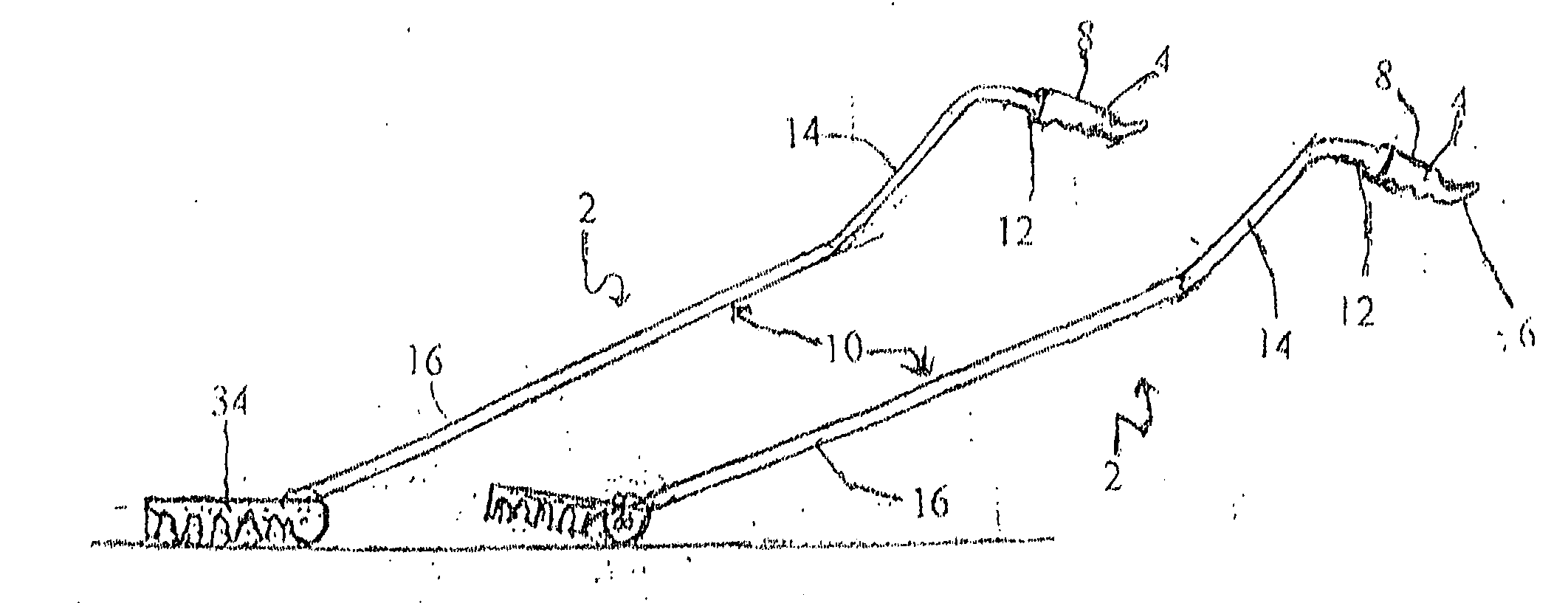
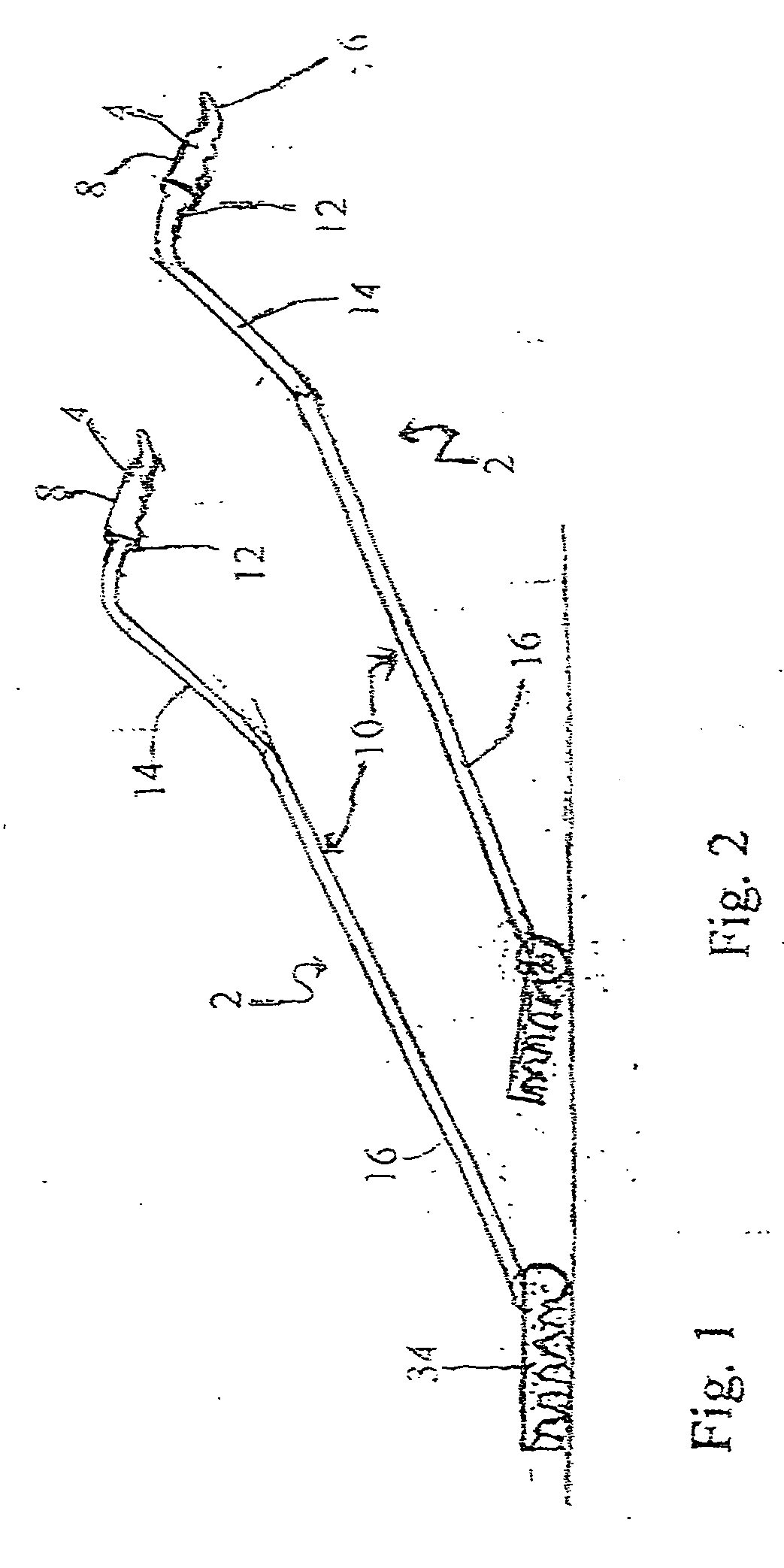
[0015] The present invention addresses the problems outlined above and seeks to eliminate them while still maintaining a rake which will clear debris or an implement for cleaning floors. The present invention is directed to a new rake or implement for cleaning floors which allows the user to remain upright under all conditions and which eliminates the step of lifting the rake or implement for cleaning floors each time it is used. The rake or implement for cleaning floors of this invention has a unique handle which allows the user to remain erect while raking or cleaning floors. The handle also allows for easy storage and has a unique handgrip which allows for easy transportL
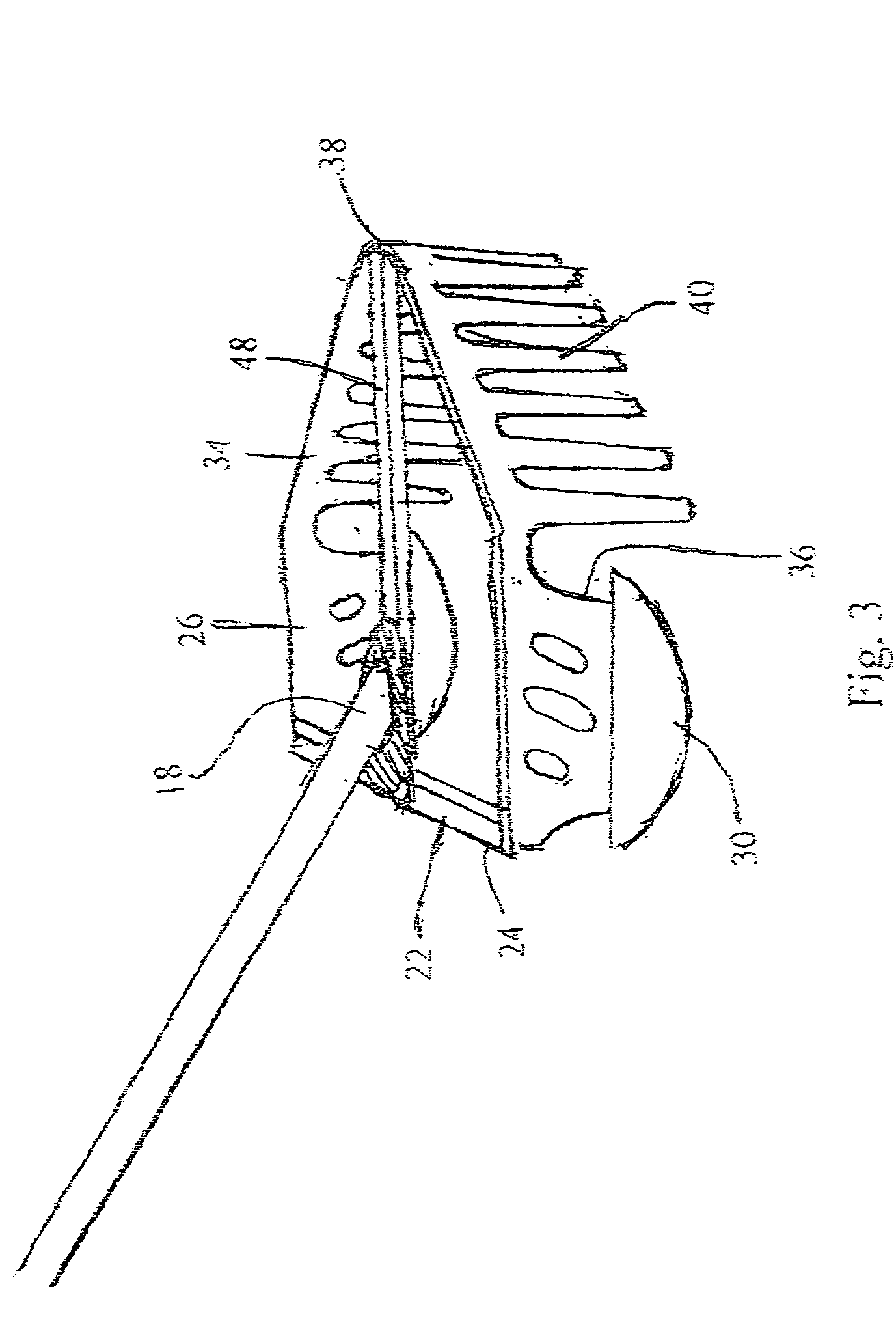
[0016] The rake of one embodiment of the present invention has a bulb-shaped front end joining sloping shoulders for penetration into hard-to-reach areas. This shape increases the debris-contaiunment width and overall containment area. The rake of a second embodiment contains a rake head featuring a single smooth arc. The rake head of a third embodiment features a rake head having a straight frame. The rake head has sidepieces which glide along the ground. The sidepieces may have bottoms which are so shaped to glide along the ground or which fit into skis or spoons which glide along the ground to enable the user to avoid lifting the rake each time the rake is used. The rake of the invention may also have an adjustable handle.
[0018] As can be readily seen from the above, this invention allows for the accomplishment of the laborious tasks of raking and cleaning floors without the usual steps of lifting and carrying the rake or implement for cleaning floors and setting the rake or implement for cleaning floors in a new position.

Problems solved by technology

Raking leaves is often arduous and time-consuming labor.
The resulting machines are rather heavy and inconvenient to use for raking loose lawn cover such as leaves.
Power machines do not appear to be practical for such purposes.
However, the raking tines are only moved over the ground and are not provided with a simulated raking action.
Leaves can soon accumulate beneath the raking tines resulting in a dragging raking action which will not rake cleanly.
Again, the attendant inconveniences and dangers of having an auxiliary power source are necessary and appear to outweigh the practical advantages of such a device, except possibly for commercial application.
As can readily be appreciated, in spite of the improvements which have been made, raking is still an arduous process.
The wheeled rakes are heavy and are not easily turned.

Method used


Image

  • Gliding rake or rolling broom
  • Gliding rake or rolling broom
  • Gliding rake or rolling broom

Examples


first embodiment

[0054] In a second, and preferred, embodiment as shown in FIGS. 4-7, the frame 34 extends from the forward end 36 of each sidepiece 26 in a gradual arc 42. About halfway to the center 38, the slope of the arc 42 becomes steeper 44 and changes again to become more gradual 46 near the center 38 so that the frame 34 reaches its greatest protrusion at the center 38 of the frame 34. Using this configuration, the rake 2 is able to contact the ground farther under shrubbery than can conventional rakes. As with the first embodiment, the tines 40 extend downwardly from the frame 34 and may be the same as or similar to tines 40 of conventional rakes. They are spaced apart the same distance as in conventional rakes. However, since the angle at which the tines 40 contact the debris is different from the angle in a conventional rake, the apparent spacing between the tines 40 is decreased and there is greater contact of the tines 40 with the debris as compared to conventional rakes.

[0055] The cro...

third embodiment

[0056] A third embodiment is disclosed in FIGS. 8-11. The rake head 20 is made up of a straight frame 34 which extends from one side to the other as in conventional rakes. On each side, a sidepiece 26 extends rearwardly from the frame 34. A crossbar 22 extends from one sidepiece 26 to the other behind the frame 34. The crossbar 22 contains a notch 48 in the center for supporting the distal end 18 of the handle 10 prior to its attachment to the frame 34. The bottom 28 of the sidepiece 26 may be rounded or a glide ski or glide spoon 32 may attached to the bottom 28 of the sidepieces 26. As in the above embodiments, a downward pressure on the handle 10 tilts the rake head 20 upwardly allowing the rake 2 to be repositioned without lifting.

[0057] As can be readily appreciated, in use the head 20 of the rake 2 is placed on the ground in the desired position, retracted toward the user, slid forward and to the side to another desired position, and retracted again. This operation does not in...


PUM


Abstract

A rake having a curved handle and a rake head which is made up of a frame having a crossbar connecting the sides of the frame and connecting to the handle. The rake head contains sidepieces which are so shaped as to enable the rake head to glide across the ground. The sidepieces may fit into ski glides or spoon glides to provide this property. The frame is straight or is arced so as to provide a large area of containment. The invention also presents a broom or squeegee having the same handle as the rake. The handle is connected to an adapter, which fits into either side of a handle connector. The broom or squeegee is also connected to wheels so that it may be moved without being lifted from the surface to be cleaned or dried.

Description

CROSS-REFERENCE TO RELATED APPLICATIONS STATEMENT REGARDING FEDERALLY SPONSORED RESEARCH OR DEVELOPMENT [0001] (Not applicable) REFERENCE TO SEQUENTIAL LISTING, A TABLE, OR A COMPUTER PROGRAM LISTING APPENDIX SUBMITTED ON A COMPACT DISC [0002] (Not applicable) BACKGROUND OF THE INVENTION [0003] 1) Field of the Invention [0004] This invention relates to rakes for gathering leaves or other debris. Also, this invention is directed to implements for cleaning floors, such as push brooms, for cleaning dirt and other debris from floors. [0005] 2) Description of the Related Art [0006] Raking leaves is often arduous and time-consuming labor. Heretofore, devices have been developed for reducing the laborious task of hand raking by providing wheeled raking devices. [0007] Power raking machines which utilize a gas or electric motor to drive a reciprocating rake head are shown in U.S. Pat. Nos. 3,777,460 and 3,417,554. These machines are often used for general lawn conditioning purposes such as ...

Claims


Application Information

Patent Timeline
Patent Type & Authority Applications(United States)
IPC IPC(8): A01D7/00
CPCA01D7/00
Inventor DUFFY, THOMAS F.
Owner DUFFY THOMAS F
Learn More