Mobile vacuum apparatus for collection of liquid or semi-liquid materials

a vacuum apparatus and semi-liquid technology, which is applied in the direction of cleaning equipment, way cleaning, animal husbandry, etc., can solve the problems of difficult transfer, inability to transfer large amounts of accumulated material to one end of the facility, and the type of machines is not particularly well-suited to the collection of liquid or semi-liquid materials. to achieve the effect of facilitating height adjustment, less material, and reducing driving speed

Active Publication Date: 2006-10-26
NUHN INDS
View PDF9 Cites 22 Cited by
  • Summary
  • Abstract
  • Description
  • Claims
  • Application Information

AI Technical Summary

Benefits of technology

[0009] It is desirable that the collected material is prevented from entering the blower vac, as obstruction of its internal moving parts can cause significant damage to the blower vac. The vacuum tank includes a vacuum outlet that may comprise two or more vacuum outlets spaced apart along the top of the tank. By using two or more vacuum outlets, the velocity through each outlet is decreased, thereby reducing the likelihood that the collected material can become entrained in the air flowing through the outlets. The outlets may be of the same size or different sizes in order to preferentially direct the collected material to different parts of the tank. Each outlet may include a primary trap to further reduce the likelihood of material escaping through the vacuum outlet, particularly when the tank is full. Any suitable primary trap design may be used and the primary trap is preferably readily cleaned by reducing the air flow through the vacuum outlet.
[0010] Air flowing from the vacuum outlet may be directed to a secondary trap for yet further reducing the likelihood that entrained debris will enter the blower vac. The secondary trap may be of any suitable design and may comprise a chamber containing a series of baffle plates that are arranged to create a serpentine path. Alternatively, the chamber may contain a plurality of perforated impingement plates stacked with the perforations in an offset relationship. The secondary trap may be similar to a knock-out pot in that it may be designed for the removal of liquid from the air flow, particularly liquid droplets. The secondary trap may be cleaned by reversing the direction of air flow through the trap and may be additionally or alternatively cleaned using a supplemental stream of air or water to flush out the contents of the trap. The secondary trap may include a drain and the drain may be directed back into the vacuum tank. The outlet of the secondary trap is preferably free of collected material or droplets and is provided to the blower vac.
[0012] The valve means may be used as part of any liquid or semi-liquid material collection system that both draws and expels material pneumatically. The valve means may be automatically adjustable or manually adjustable. The valve means may comprise a three-way valve mechanism that permits selection of a single flow path from two different flow paths, for example and L-ported ball valve that may be alternated between two flow paths. The valve means may comprise a pair of check valves, one check valve in each of the intake and exhaust flow paths. The check valves may be oppositely oriented to permit air to flow into the valve means through only one flow path (the intake flow path) and out of the valve means by only the other flow path (the exhaust flow path). In this manner, the valve means is automatically adjustable in response to a change in the direction of flow through the blower vac. The valve means may include a valve chamber and the check valves need not necessarily both be located in the valve chamber. The valve means is particularly advantageous in allowing an air intake and exhaust of the system to be separated, thereby permitting the intake to be elevated with respect to the material being collected and the exhaust to be located distantly from the operator. The elevated exhaust reduces the likelihood of debris entering the blower vac when blowing air into the tank and the distant exhaust improves operator health and safety.
[0014] The suction inlet may be height adjustable independently of any height adjustment of the collection means in response to the quantity of material being collected; this permits a scraping element of the collection means to remain in contact with the floor surface while allowing the suction inlet to be adjusted relative in height thereto in response to a large quantity of material being collected. Any suitable mechanism may be employed to adjust the height of the suction inlet. The suction inlet is preferably connected to the vacuum inlet by a flexible connection in order to facilitate the height adjustment. By setting the suction inlet closer to the floor surface that the material is being collected from more material may be collected, thereby leaving less material in the collection means at the end of a pass through an alley. However, if set close to the floor, the suction inlet will have more material to pick-up and driving speed may have to be reduced. There is therefore an optimal trade-off between speed and completeness of collection. A snorkel may be provided alongside the suction inlet for introducing a small quantity of air into the material as it is being collected. This small quantity of air is entrained with the material and makes it easier to lift from the floor and easier to pneumatically convey, particularly for materials with a thick consistency. The snorkel may include a small valve to set the quantity of air provided to the suction inlet according to the consistency of the material being collected.
[0015] The collection means may include a variable width mechanism. The variable width mechanism is particularly useful in the collection of manure from alleys or gutters, as it allows the collection means to fit the width of the alley or gutter and reduces the likelihood of manure escaping around the sides of the collection means. The collection means may include wings that are pivotally attached to each side of the collection means and able to pivot about a vertical pivot axis. The wings may be biased outwardly towards or against the sidewalls of the alley or gutter and may resiliently adapt to changes in the width of the gutter by pivoting about the vertical pivot axis. The wings may move about the vertical pivot axis in response to a change in the distance between the side-wall of the alley and the collection means. The wings may be biased by a spring means or a suitable fluid cylinder arrangement, such as a pneumatic or hydraulic fluid displacement cylinder, a captive gas shock absorber, or a combination thereof. The wings may automatically adjust to the width of the alley or gutter or may be manually adjusted by an operator of the apparatus. The adjustment may be conducted using controls within the towing vehicle. The wings may include skid plates or wear strips to reduce the likelihood of damaging the wings due to operator driving error.
[0016] The discharge outlet is provided at the rear of the vacuum tank. The discharge outlet may be connected to any manure distribution system suitable for liquid or semi-liquid manure, such as a spreader plate or sub-surface injection system. Alternatively, the discharge outlet may be connected via a fluid conduit for transferring the manure to a separate spreading apparatus or a holding vessel. The vacuum inlet is provided at the front of the tank, preferably in a lower half thereof below the horizontal midline of the tank. Filling the tank from the front and discharging the tank through the rear causes a flushing of the collected materials through the tank. This causes substantially all of the material in the tank to be discharged and mitigates material build-up in the front of the tank. During collection, a remotely operable valve on the discharge outlet is closed to prevent inadvertent leakage from occurring. During tank discharge, a remotely operable valve on the vacuum inlet is closed to prevent material from being discharged through the collection means.

Problems solved by technology

The manure is typically liquid or semi-liquid and is often difficult to transfer in this manner, as it escapes around the sides of the scraper blade or bucket.
In addition, with the very large facilities that are becoming quite common in modern dairy farming, sometimes with an overall length in excess of 1000 feet, the quantity of accumulated material is too great to transfer to one end of the facility.
These types of machines are not particularly well-suited to the collection of liquid or semi-liquid materials such as animal waste.
Moreover, they lack any type of collection means for mounting beneath the apparatus to direct the collected material to the suction inlet when the apparatus is driven over the material, making them difficult to use in large scale mobile cleanup operations.
This machine is not suitable for the cleanup of liquid or semi-liquid materials.
However, in mounting the scraper blade at the rear of the apparatus, the manure is compacted prior to being collected, making it difficult to separate from the barn floor and difficult to convey pneumatically.
This leads to an accumulation of manure in the front of the tank that diminishes tank capacity after repeated use.
The accumulated manure must be periodically cleaned out through manual access hatches, which is a dangerous and unpleasant task.
Also, the apparatus makes use of separate blower and vacuum pumps, which creates mechanical complexity and increases down time.

Method used


Image

  • Mobile vacuum apparatus for collection of liquid or semi-liquid materials
  • Mobile vacuum apparatus for collection of liquid or semi-liquid materials
  • Mobile vacuum apparatus for collection of liquid or semi-liquid materials

Examples


Embodiment Construction

[0026] In describing the figures, like features are referred to by like reference numerals. Although not all features indicated on a particular drawing are necessarily described with reference to that drawing, all of the features are described with reference to at least one of the drawings.

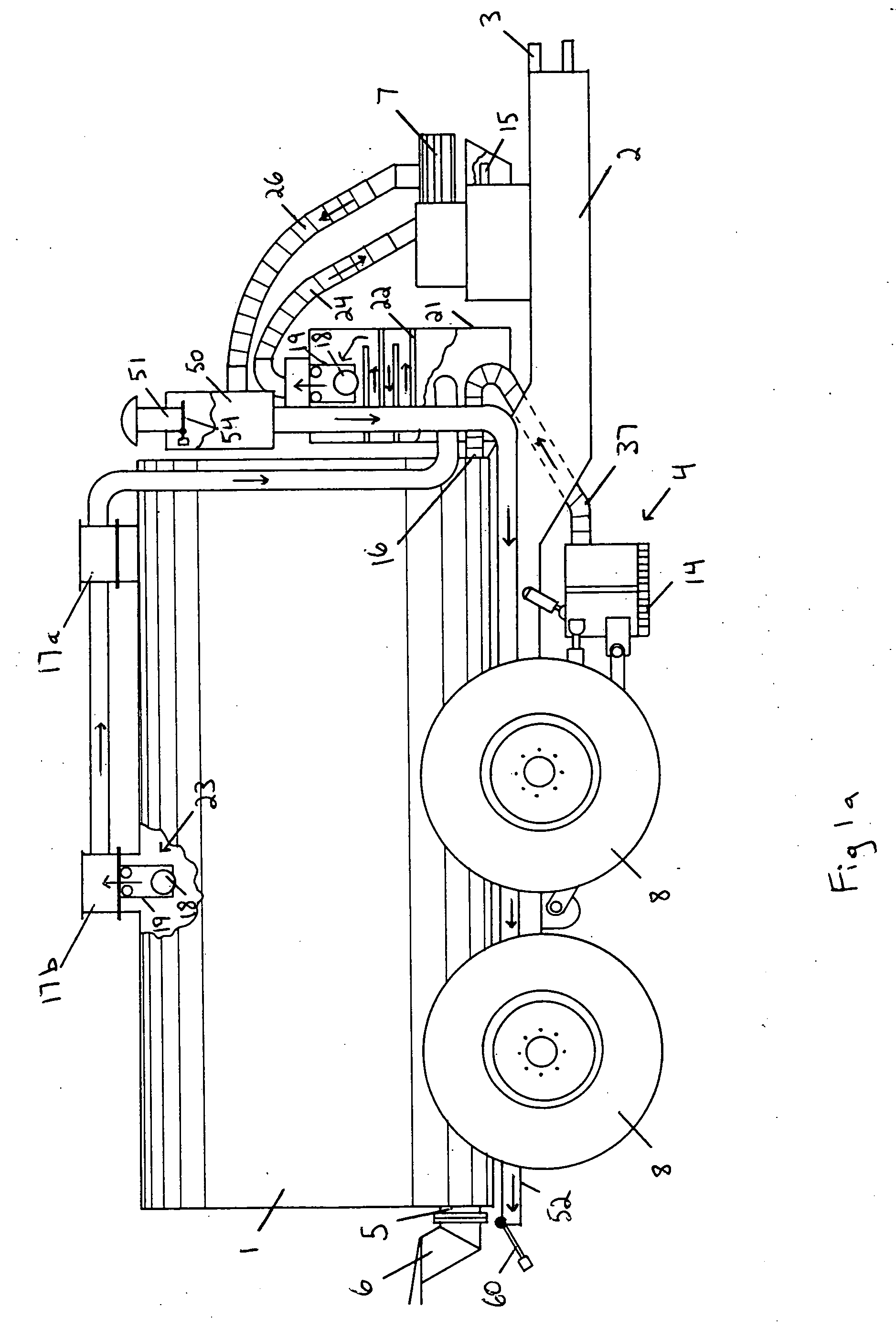
[0027] Referring to FIGS. 1a and 1b, the mobile vacuum apparatus comprises a vacuum tank 1 mounted on a frame 2 having a front and rear with a hitch means 3 for connection to a towing vehicle (not shown) at the front of the frame. A collection means 4 is mounted to the underside of the frame 2 at the front thereof, forward of a discharge outlet 5 of the vacuum tank 1. A spreader means 6 is attached to a flange on the discharge outlet 5. A set of tandem wheels 8 is mounted to the underside of the frame 2 using a walking-axle arrangement as is conventionally known.

[0028] A blower vac 7 is provided at the front of the frame 2. The blower vac 7 is a positive displacement rotary vane pump (in a prefe...


PUM


Abstract

The apparatus comprises a vacuum tank with a front-mounted collection means thereunder The collection means is a V-shaped scraper with a height adjustable suction inlet at the apex thereof. The collection means has a pair of laterally adjustable pivoting wings for varying its width to correspond to that of an alley or gutter. The suction inlet may be equipped with a snorkel to introduce a small quantity of air as an aid in entraining thick-consistency materials. A blower vac is used to both draw air into and blow air through the vacuum tank. A valve means comprising a pair of oppositely oriented check valves is used to alternate flow paths between a lowered rearward exhaust during collection and an elevated intake during tank discharge.

Description

FIELD OF THE INVENTION [0001] The invention relates to the mobile pneumatic collection of liquid or semi-liquid materials such as animal manure. More specifically, the invention relates to a mobile vacuum apparatus having a collection means mounted thereunder that directs the liquid or semi-liquid materials into a suction inlet when the apparatus is driven through the materials. BACKGROUND OF THE INVENTION [0002] Animal husbandry facilities, such as dairy or hog barns, include alleys or gutters for manure collection. Vehicles such as tractors or skid-steer loaders are equipped with scraper blades or front-end bucket systems to transfer manure accumulated in the alley or gutter to one end of the barn for removal and disposal. The manure is typically liquid or semi-liquid and is often difficult to transfer in this manner, as it escapes around the sides of the scraper blade or bucket. In addition, with the very large facilities that are becoming quite common in modern dairy farming, so...

Claims


Application Information

Patent Timeline
Patent Type & Authority Applications(United States)
IPC IPC(8): E01H1/08
CPCA01K1/0103A01C3/04A01K1/0128Y02A40/28
Inventor NUHN, DENNIS
Owner NUHN INDS
Why Eureka
Try Eureka