
Storage system with automatic redundant code component failure detection, notification, and repair

a technology of redundant code and storage controller, applied in the direction of code conversion, instruments, code execution, etc., can solve the problems of corrupted stored programs, one or more bad sectors of the device, and relatively slow execution of programs from flash memory, so as to reduce the likelihood that the controller fails to boo

Inactive Publication Date: 2006-10-19
DOT HILL SYST
View PDF59 Cites 80 Cited by
  • Summary
  • Abstract
  • Description
  • Claims
  • Application Information

AI Technical Summary

Benefits of technology

[0012] In another aspect, the present invention provides a method for improving the data availability characteristics of a RAID system. The method includes executing a first program on a processor of the RAID system. The method also includes the first program detecting that a first copy of a second program is failed. The first copy of the second program is stored in a non-volatile memory of the RAID system. The method also includes the first program repairing the failed first copy of the second program in the non-volatile memory using a second copy of the second program stored in the non-volatile memory.
[0014] An advantage of the automatic detection and repair of failed copies of the programs is that it automatically maintains redundant copies of the programs to achieve fault-tolerance, thereby potentially reducing the likelihood that a controller will fail to boot by avoiding a situation in which all the copies of a program are bad. It also enables a user to replace a failing controller when necessary by warning the user of program copy failures.

Problems solved by technology

However, execution of the programs from the FLASH memory is relatively slow.
A characteristic of sectored FLASH memory devices is that one or more sectors of the device may be bad and other sectors may be good.
Even a single bad sector may result in corruption of the stored programs such that the stored programs will fail to boot.
For example, if a sector storing the loader program is bad (or the entire FLASH device is bad), then the loader program will fail to boot; in particular, the loader program will not load the application programs into RAM and transfer control thereto.
Similarly, if a sector storing the application programs is bad (or the entire FLASH device is bad), then the application programs will fail to boot; in particular, although the loader program may load the application programs into RAM and transfer control thereto, the application programs will fail to operate the controller properly to transfer data between the host computer and the disk drives.
Bad FLASH memory sectors or entire bad FLASH memory devices may result during the manufacture of the FLASH memory device.
Additionally, bad sectors may develop in the controller manufacturing process.
Still further, bad sectors may develop in the field during use of the controller by the end user.
Consequently, the controller may fail to properly program in the field marginal sectors of the FLASH device that were correctly programmed when the controller was manufactured.
Any of these types of bad sectors in the FLASH memory or an entire bad FLASH memory device may result in the controller failing to boot.
However, in some operating environments that do not require the high level of data availability that redundant controllers provide, the cost is too high; rather, a single controller is desirable in these environments.
Still further, even in a redundant controller configuration, it is unacceptable in certain mission-critical environments, such as video-on-demand or financial applications or medical applications, to have one of the redundant controllers failed for a prolonged period.
Thus, in the above-mentioned scenarios, it is unacceptable for a controller to fail to boot due to a bad FLASH memory sector or device.

Method used


Image

  • Storage system with automatic redundant code component failure detection, notification, and repair
  • Storage system with automatic redundant code component failure detection, notification, and repair
  • Storage system with automatic redundant code component failure detection, notification, and repair

Examples


Embodiment Construction

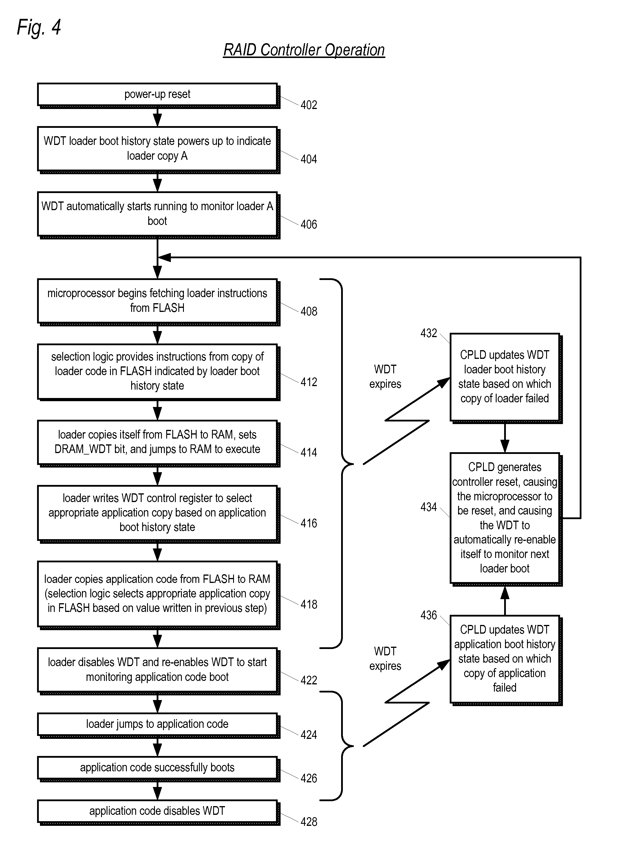
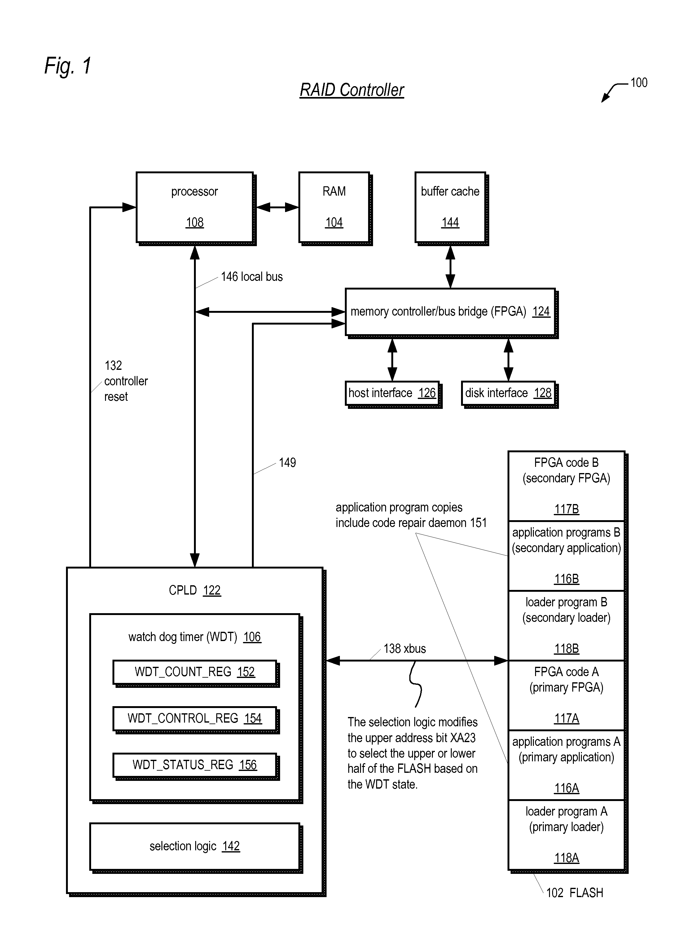
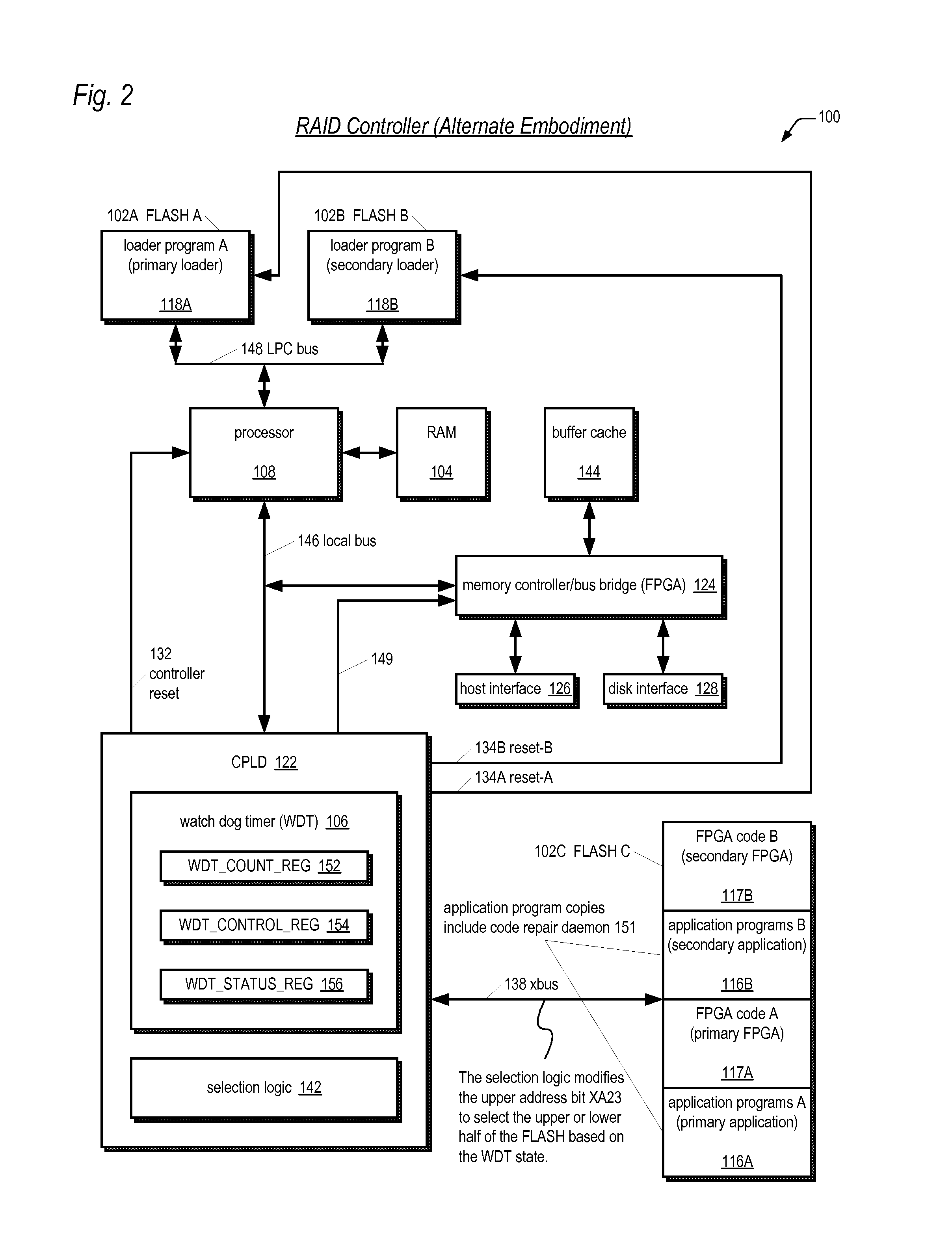
[0027] Referring now to FIG. 1, a block diagram illustrating a RAID controller 100 according to one embodiment of the present invention is shown. In one embodiment, the controller 100 may be one of a pair of active-active or active-passive redundant fault-tolerant RAID controllers for providing high data availability. In another embodiment, the controller 100 may be a single controller. Advantageously, in any system configuration, the controller 100 includes redundant copies of its stored programs and a mechanism for selectively attempting to boot different ones of the redundant copies until successfully booting as long as at least one copy is good. In one embodiment, the controller 100 includes a watch dog timer which automatically starts running each time the controller 100 attempts to boot a copy of the stored programs. If the timer expires, the timer resets the controller 100 after updating state used by selection logic to select another copy to attempt to boot. Additionally, ad...


PUM


Abstract

A RAID system includes a non-volatile memory storing a first program and first and second copies of a second program, and a processor executing the first program. The first program detects the first copy of the second program is failed and repairs the failed first copy in the non-volatile memory using the second copy. The failures may be detected at boot time or during normal operation of the controller. In one embodiment, the failure is detected via a CRC check. In one embodiment, the controller repairs the failed copy by copying the good copy to the location of the failed copy. In one embodiment, the system includes multiple controllers, each having its own processor and non-volatile memory and program that detects and repairs failed program copies. The programs include a loader, an application, FPGA code, CPLD code, and a program for execution by a power supply microcontroller.

Description

CROSS REFERENCE TO RELATED APPLICATION(S) [0001] This application is a continuation-in-part of application Ser. No. 11 / 140,106 (Atty. Docket CHAP.0123) filed May 27, 2005, which is hereby incorporated by reference for all purposes, which claims the benefit of U.S. Provisional Application Ser. No. 60 / 667,861 (Atty. Docket CHAP.0123) filed Apr. 1, 2005, which is hereby incorporated by reference for all purposes. [0002] This application claims the benefit of U.S. Provisional Application Ser. No. 60 / 694,444 (Atty. Docket CHAP.0130) filed Jun. 27, 2005, which is hereby incorporated by reference for all purposes.FIELD OF THE INVENTION [0003] The present invention relates in general to the field of storage controllers, and particularly to fault-tolerance of stored programs in storage controllers. BACKGROUND OF THE INVENTION [0004] Redundant Array of Inexpensive Disk (RAID) systems have become the predominant form of mass storage systems in most computer systems today that are used in appli...

Claims


Application Information

Patent Timeline
Patent Type & Authority Applications(United States)
IPC IPC(8): H03M13/00
CPCG06F11/0727G06F11/1417G06F11/0781G06F11/076
Inventor LINTZ, DWIGHT OLIVER JR.WANG, YUANRU FRANK
Owner DOT HILL SYST
Learn More