
Poynting-vector based method for determining the bearing and location of electromagnetic sources

a technology of radiated field loss and vector, which is applied in the direction of resistance/reactance/impedence, voltage-current phase angle, instruments, etc., can solve the problems of transmission loss in all electric power systems involving electricity generation, transmission and load, and one form of loss that is virtually impossible to elimina

Inactive Publication Date: 2006-10-19
LAWRENCE LIVERMORE NAT SECURITY LLC
View PDF5 Cites 28 Cited by
  • Summary
  • Abstract
  • Description
  • Claims
  • Application Information

AI Technical Summary

Benefits of technology

"The present invention provides a method and apparatus for detecting and locating radiating electrical sources, such as A.C. generators, transmitters, electrical conductors, and loads. The techniques and devices enable spatial mapping of fields and remote source characterization and temporal assessment of electrical usage for stationary objects as well as for tracking movement of any radiating mobile source / load systems. The invention can be used in various applications, such as in cars, trucks, tanks, boats, submarines, airplanes, and space vehicles."

Problems solved by technology

All electric power systems that involve electricity generation, transmission and loads are subject to transmission loss.
One form of loss that is virtually impossible to eliminate is the radiated field loss (NF & FF) that comes with changing loads or loads that respond to applied voltage in a nonlinear fashion in a power generation and utilization system.
This is energy loss due to the non-ideal flow of electrical currents resulting in a radiated electromagnetic field that is highly dependent on the specifics of the generator and loads and the result of an imbalanced system.

Method used


Image

  • Poynting-vector based method for determining the bearing and location of electromagnetic sources
  • Poynting-vector based method for determining the bearing and location of electromagnetic sources
  • Poynting-vector based method for determining the bearing and location of electromagnetic sources

Examples


Embodiment Construction

[0018] Referring now to the drawings, specific embodiments of the invention are shown. The detailed description of the specific embodiments, together with the general description of the invention, serves to explain the principles of the invention.

[0019] Unless otherwise indicated, numbers expressing quantities of ingredients, constituents, reaction conditions and so forth used in the specification and claims are to be understood as being modified by the term “about.” Accordingly, unless indicated to the contrary, the numerical parameters set forth in the specification and attached claims are approximations that may vary depending upon the desired properties sought to be obtained by the subject matter presented herein. At the very least, and not as an attempt to limit the application of the doctrine of equivalents to the scope of the claims, each numerical parameter should at least be construed in light of the number of reported significant digits and by applying ordinary rounding t...


PUM


Abstract

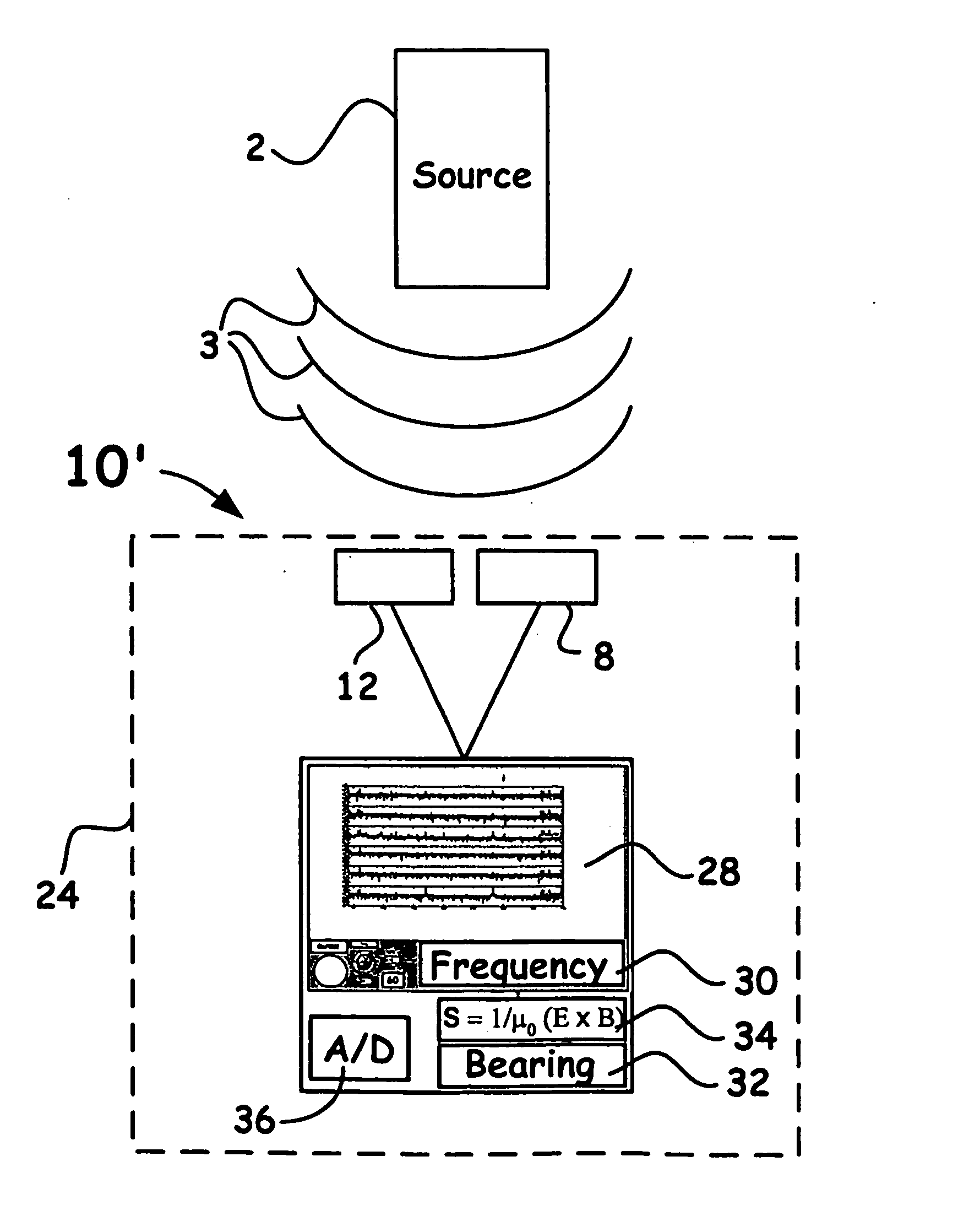
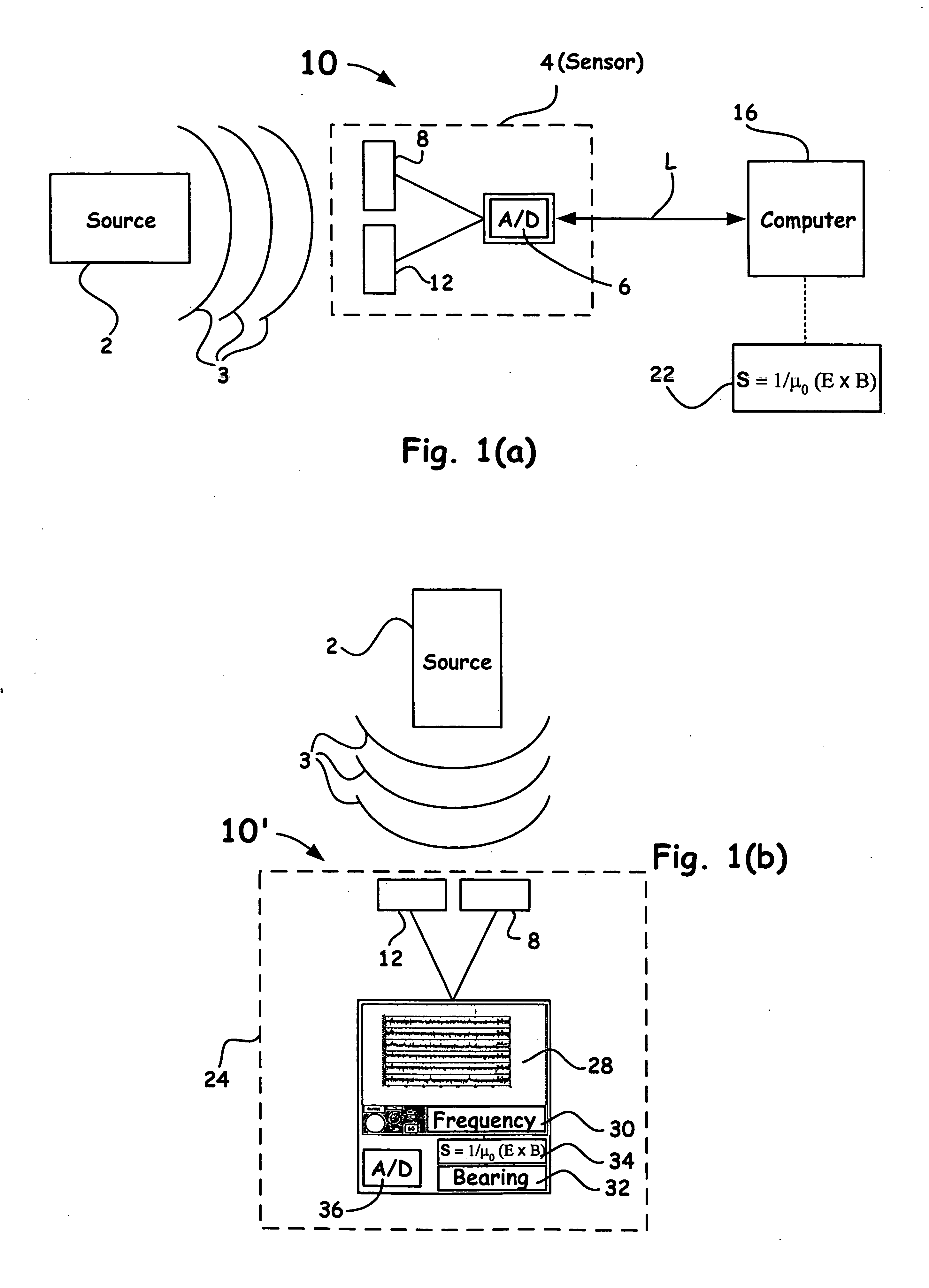
A method and apparatus is utilized to determine the bearing and / or location of sources, such as, alternating current (A.C.) generators and loads, power lines, transformers and / or radio-frequency (RF) transmitters, emitting electromagnetic-wave energy for which a Poynting-Vector can be defined. When both a source and field sensors (electric and magnetic) are static, a bearing to the electromagnetic source can be obtained. If a single set of electric (E) and magnetic (B) sensors are in motion, multiple measurements permit location of the source. The method can be extended to networks of sensors allowing determination of the location of both stationary and moving sources. It is emphasized that this abstract is provided to comply with the rules requiring an abstract which will allow a searcher or other reader to quickly ascertain the subject matter of the technical disclosure. It is submitted with the understanding that it will not be used to interpret or limit the scope or the meaning of the claims.

Description

RELATED APPLICATION [0001] This application claims priority from U.S. Provisional Patent Application No. 60 / 671,793, entitled “A POYNTING-VECTOR BASED METHOD FOR DETERMINING THE BEARING AND LOCATION OF ELECTROMAGNETIC SOURCES,” filed on Apr. 15, 2005, and is incorporated by reference in its entirety.[0002] The United States Government has rights in this invention pursuant to Contract No. W-7405-ENG48 between the United States Department of Energy and the University of California for the operation of Lawrence Livermore National Laboratory.BACKGROUND OF THE INVENTION [0003] 1. Field of the Invention [0004] The present invention relates to the detection of radiating electromagnetic waves, and more particularly, the present invention relates to the detection and location of radiating sources, often low-frequency radiating electromagnetic sources operating within the near-field, using Poynting vector E and B field measurements. [0005] 2. Description of Related Art [0006] Near-field radia...

Claims


Application Information

Patent Timeline
Patent Type & Authority Applications(United States)
IPC IPC(8): G06F19/00G06F3/033G06F3/0346
CPCG01R29/0892
Inventor SIMONS, DAVID J.CARRIGAN, CHARLES R.HARBEN, PHILIP E.KIRKENDALL, BARRY A.SCHULTZ, CRAIG A.
Owner LAWRENCE LIVERMORE NAT SECURITY LLC
Learn More