
Vehicle lamp with a light guide of a multi-member configuration

a multi-member configuration and light guide technology, applied in the direction of fibre light guide, lighting and heating apparatus, instruments, etc., can solve the problems of inability to fit a more greatly curved shape, inability to achieve light emission in particular inclined rearward, etc., to achieve enhanced light output and improve light emission characteristics

Inactive Publication Date: 2006-10-19
FER FAHRZEUGELEKTRIK GMBH
View PDF8 Cites 27 Cited by
  • Summary
  • Abstract
  • Description
  • Claims
  • Application Information

AI Technical Summary

Benefits of technology

[0008] Another object of the present invention is to provide a vehicle lamp affording improved light emission characteristics in terms of direction and spread angle.
[0009] A further object of the invention is to provide a vehicle lamp with integrated light guide means and operable to afford enhanced light output of a desired configuration.
[0010] Still a further object of the invention to provide a light guide for a lamp such as a vehicle lamp, which can be effective to produce light emission of a respectively desired configuration in a desired directional space.
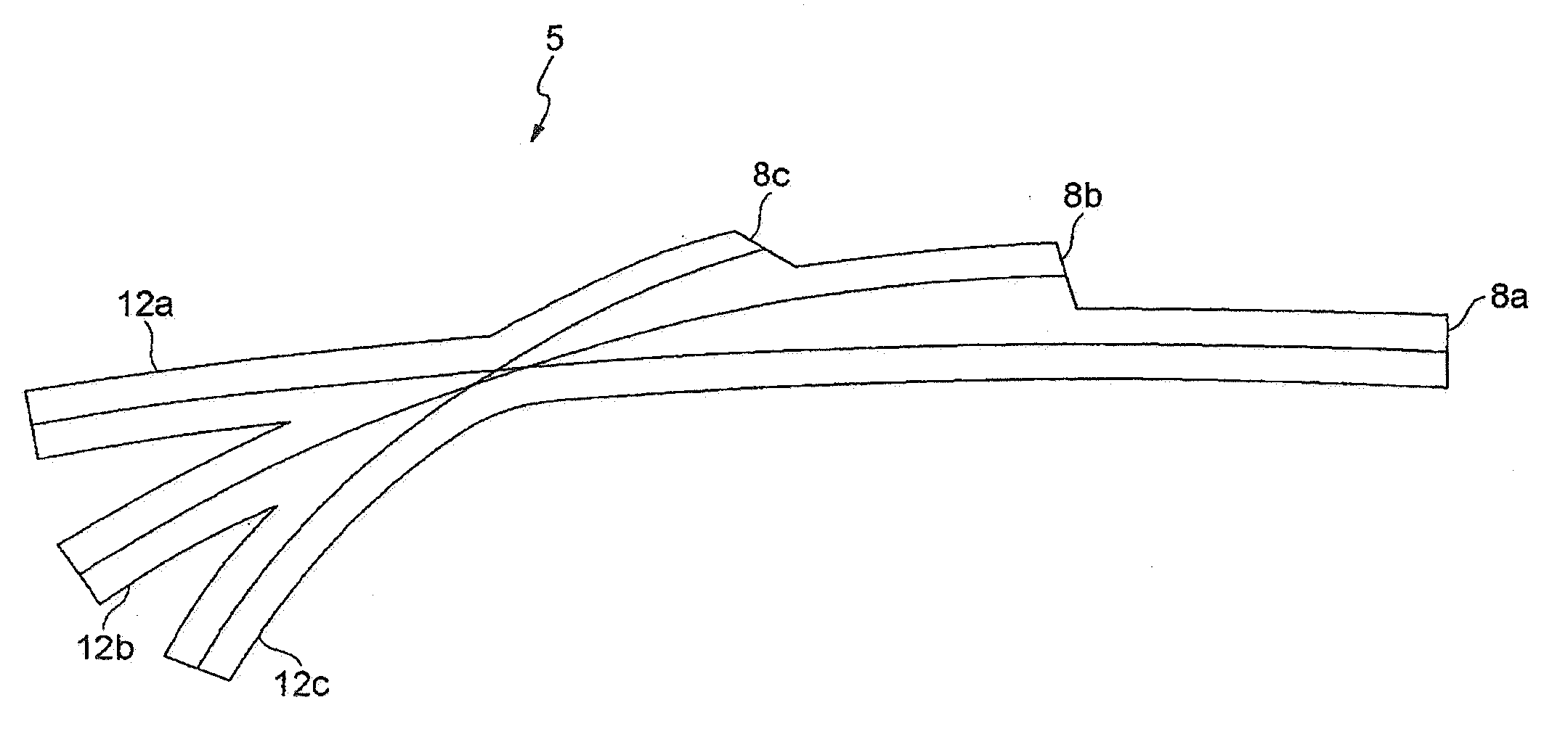
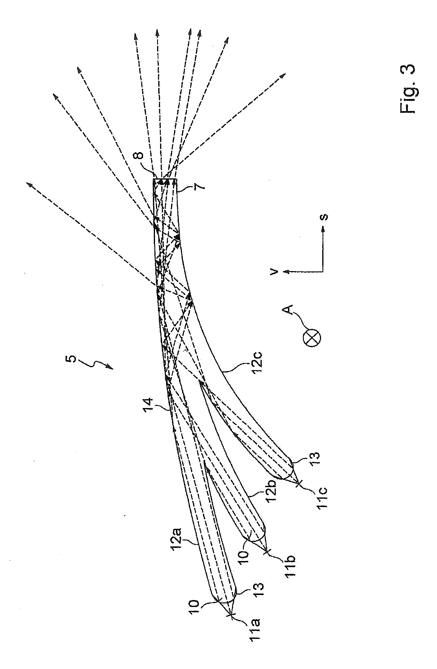
[0013] As will be seen from the description hereinafter of preferred embodiments of the invention the light guide of the vehicle lamp is of a multi-member configuration, that is to say having a plurality of limbs which preferably extend in mutually juxtaposed relationship and which are curved to differing degrees. In that case the light is preferably introduced in end relationship at the individual coupling-in ends of the limbs. The differing curvature results in a different beam path in each of the limbs, whereby the light beams impinge at different angles of incidence on the side and coupling-out surfaces of the light guide. The multi-member configuration therefore affords a substantial advantage in that the light guided in the light guide involves very different directions and is thus also coupled out in very different directions at the coupling-out surface. In that way it is now possible for the light to be emitted in a relatively wide solid angle which complies with the relevant regulations, even if the coupling-out end of the light guide extends substantially in a lateral direction. The angular range in which the light is emitted is determined in particular by the curvature of the individual limbs and can be adjusted in the desired manner.
[0021] In order to boost the coupling-out effect of light in the direction of travel of a vehicle to which the lamp is fitted the light guide can have light-diffusing means at a longitudinal side. Thus for example the surface of the rearward longitudinal side can be of a particularly rough nature. Alternatively other diffusing structures could also be provided at the rear side of the light guide.
[0024] The light sources arranged at the ends of the individual limbs are preferably connected in series. Particularly in the case of LEDs, that has the advantage that an unnecessarily high series resistor does not have to be used upstream of each LED. The light sources are also preferably arranged on the same circuit board with a flexible circuit board being particularly suitable in that connection.

Problems solved by technology

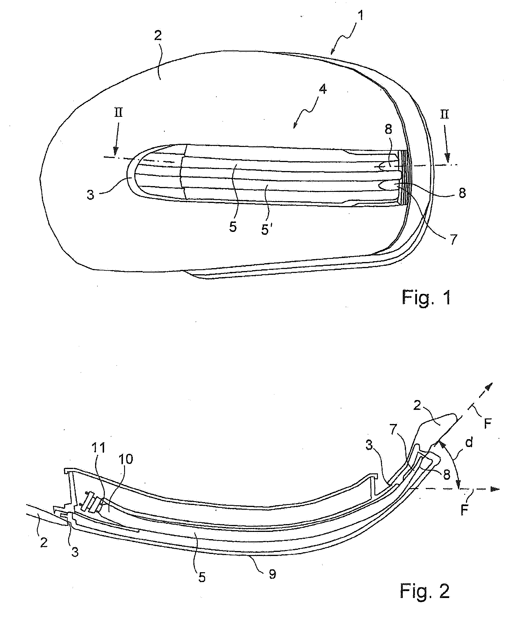
In such cases, for reasons relating to structural technology, it is not possible to fit a more greatly curved light guide 5 whose coupling-out end 7 points inclinedly rearwardly.
Light emission in particular inclinedly rearwardly, as is required by the statutory regulations, therefore cannot be achieved.

Method used


Image

  • Vehicle lamp with a light guide of a multi-member configuration
  • Vehicle lamp with a light guide of a multi-member configuration
  • Vehicle lamp with a light guide of a multi-member configuration

Examples


Embodiment Construction

[0032] With regard to the description of FIGS. 1 and 2, attention is directed to the introductory part of this description set forth hereinbefore.

[0033] Referring now to FIG. 3, shown therein is a plan view from above of a multi-member integrally formed light guide 5 which for example can be fitted in a side flashing lamp of an external rear view mirror or in a side riding lamp of a vehicle. The light guide 5 can be made as is usually the case from a plastic material. The lamp for that purpose can have mounting means for installation thereof in vehicle bodywork or in a cover cap of an external rear view mirror of a vehicle.

[0034] The relative position of the vehicle is indicated by the arrows V, S, wherein V indicates a forward direction of the vehicle and S indicates a lateral direction of the vehicle. The side of the light guide 5, which is towards the vehicle, is the side which is at the left in the Figure.

[0035] At the vehicle side the light guide 5 includes three limbs 12a-1...


PUM


Abstract

The invention concerns a vehicle lamp comprising an elongate light guide, and a light source which is arranged at one end of the light guide and whose light is coupled into the light guide and at least partially passed to an oppositely disposed coupling-out end where it is coupled-out. The light guide is of a multi-member configuration and on the side towards the vehicle has a plurality of limbs which are curved to differing degrees.

Description

CROSS-REFERENCES TO RELATED APPLICATIONS [0001] This application claims the priorities of German patent applications Serial Nos 10 2005 014 195.1 filed Mar. 29, 2005 and 10 2005 019 093.6 filed Apr. 25, 2005, the subject-matter of which is incorporated herein by reference. FIELD OF THE INVENTION [0002] The invention relates to a vehicle lamp with an elongate light guide and a light guide for a lamp. BACKGROUND OF THE INVENTION [0003] Bar-shaped light guides are frequently used in vehicle lamps such as for example side marking or riding lamps or side flashing lamps which are integrated into the external mirror of vehicles. They enjoy in particular the advantage that the desired light distribution can be implemented using relatively simple means and very inexpensively. [0004] The structure and function of a typical vehicle lamp with a bar-shaped light guide are described in greater detail hereinafter with reference to FIGS. 1 and 2. FIG. 1 shows a side flashing lamp 4 which is known f...

Claims


Application Information

Patent Timeline
Patent Type & Authority Applications(United States)
IPC IPC(8): A22B3/06
CPCB60Q1/0683B60Q1/2665F21S48/215F21S48/2237G02B6/0075F21S48/2268F21S48/2281G02B6/0006G02B6/0008F21S48/2262F21S43/14F21S43/237F21S43/243F21S43/245F21S43/249
Inventor GOTTHARDT, FRANK
Owner FER FAHRZEUGELEKTRIK GMBH
Learn More