
All-in-one polish dispenser and wiper

Active Publication Date: 2006-10-19
SC JOHNSON & SON INC +1
View PDF32 Cites 12 Cited by
  • Summary
  • Abstract
  • Description
  • Claims
  • Application Information

AI Technical Summary

Benefits of technology

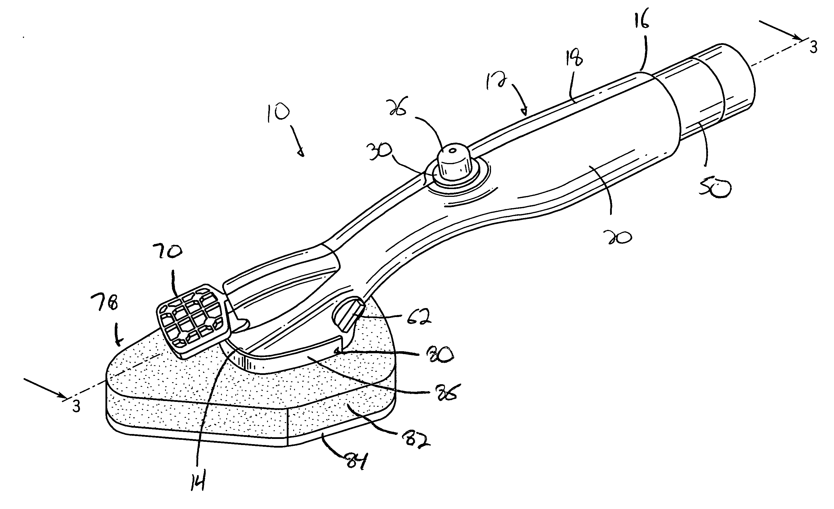
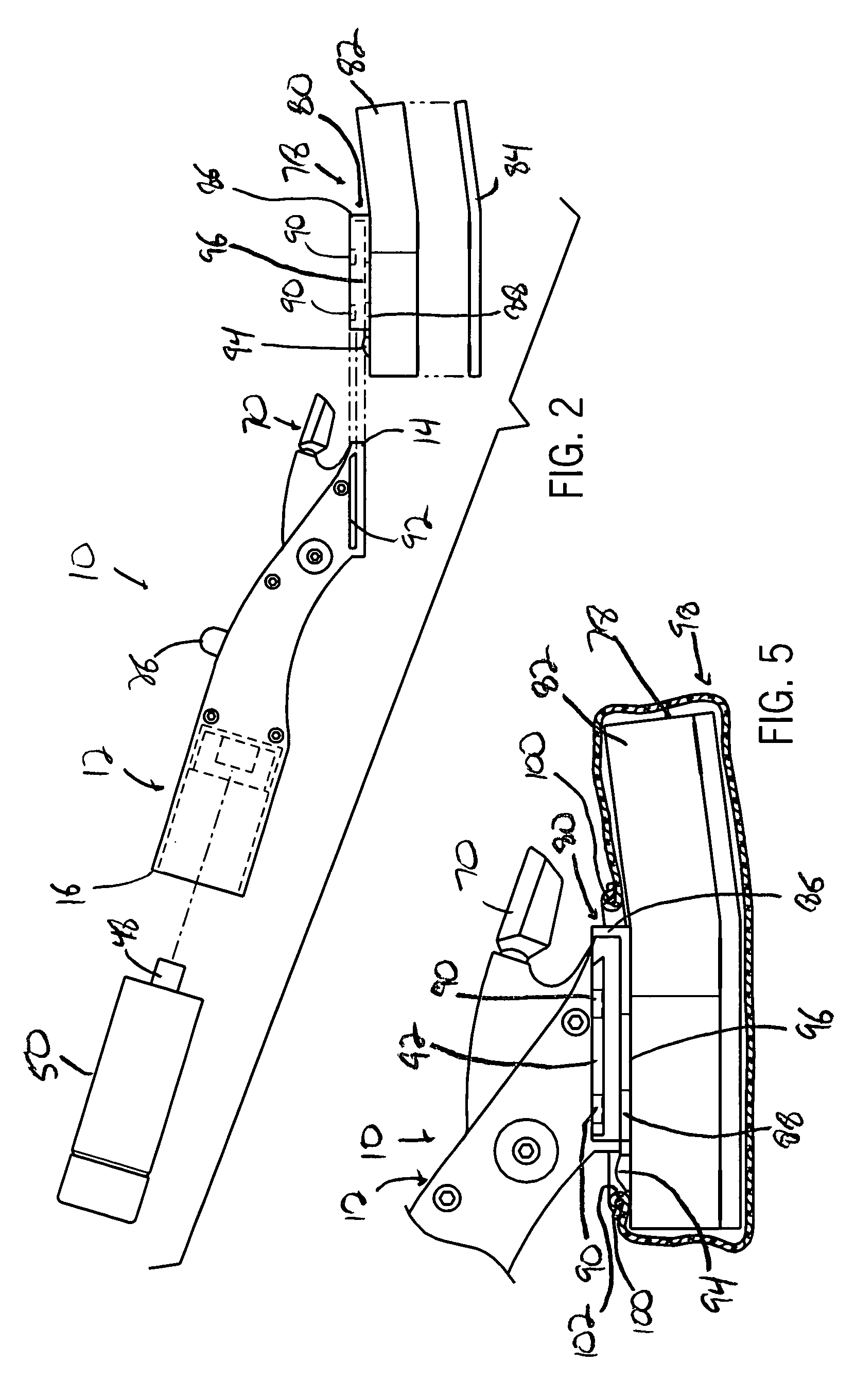
[0007] It is a primary object of the present invention to provide a cleaning device including a dispensing mechanism that allows for dispensing of a cleaning or polishing solution from the device either through or to one side of a solution applying member disposed on the device. The dispensing mechanism includes a rotatable valve capable of selectively enabling the solution to be dispensed from the device by the actuation of the mechanism through either a spray nozzle disposed on the device or through the dispersion of the solution through the applying member. The dispensed solution is provided from a solution reservoir or container that is releasably connectable to the device. The container enables the solution to be withdrawn as desired from the container through the use of the dispensing mechanism until the total amount of solution within the container is depleted, at which time the container can be easily disengaged from the device for disposal, and a full replacement container can be secured to the device for continued usage of the device.
[0009] According to still another aspect of the present invention, the device is provided with a simplified construction allowing for easy construction and assembly of the device, including the selective dispensing mechanism and the disposable solution applying member, to greatly reduce the time and cost associated with manufacturing and assembling the device.

Problems solved by technology

However, on most occasions the cleaning solution is dispensed into the applying member approximately at the center of the applying member, meaning that a significant amount of the solution must be dispensed into the applying member for the solution to disperse to an applying edge or surface of the applying member.
This can result in a situation where a large amount of solution that is utilized in wetting the applying member is wasted, as the solution normally evaporates out of the applying member when the device is not in use.

Method used


Image

  • All-in-one polish dispenser and wiper
  • All-in-one polish dispenser and wiper
  • All-in-one polish dispenser and wiper

Examples


Embodiment Construction

[0018] With reference to the drawing figures in which like reference numerals designate like parts throughout the disclosure, the polishing and cleaning device constructed according to the present invention is indicated generally at 10 in FIG. 1. The device 10 includes a handle 12 having a forward end 14 and a rearward end 16, and is formed of a pair of opposed halves or sections 18 and 20 connected to one another to form the handle 12. The sections 18 and 20 can be formed of any suitable material, but preferably are formed of a rigid, plastic material such that the sections 18 and 20 can be formed in any suitable plastic molding process. Further, the sections 18 and 20 can be joined to one another to form the handle 12 utilizing any suitable mechanical structures, such as pins 22 in section 18 that are fixedly received within bores 24 in section 20, any suitable heat-sealing means, or any suitable adhesive means, as well as any combination thereof. The handle 12, and sections 18 an...


PUM


Abstract

The present invention is a device for applying a cleaning or polishing solution to a surface and wiping the solution over the surface. The device includes a rotatable valve that allows for the dispensing of the solution through either a nozzle that sprays the solution in front of a disposable sponge-like pad secured to the device, or directly into the pad for application to the surface by the pad. The device also includes a rearward opening that releasably receives a container of the solution to be dispensed from the device. When the container is empty, the container is removed and replaced in order to allow the device to be used in a generally continuous manner for cleaning and polishing the surface. The disposable pad connected to the device may also include a cleaning surface capable of picking up dust, dirt and other debris in addition to applying the polishing and cleaning solutions to the surface.

Description

FIELD OF THE INVENTION [0001] The present invention relates to an apparatus for polishing and cleaning surfaces, and more specifically to a device capable of dispensing a polishing and cleaning composition and wiping the composition onto the surface simultaneously. BACKGROUND OF THE INVENTION [0002] Numerous devices have been developed over the years for dispensing a cleaning or polishing solution and simultaneously applying or wiping the solution off of the surface. The majority of these devices take the form of a mechanism that selectively dispenses an amount of a cleaning and / or polishing solution into a solution or fluid applying member when an actuator, such as an actuating button is pressed. The solution is dispensed directly into the solution applying member, e.g., a sponge, so that the solution disperses throughout the solution applying member for application to the surface. [0003] However, on most occasions the cleaning solution is dispensed into the applying member approxi...

Claims


Application Information

Patent Timeline
IPC IPC(8): B08B7/00A47L13/30
CPCA47L1/15B08B1/00A47L13/30A47L13/26B05B1/1636
Inventor KNOPOW, JEREMY F.GUNDLACH, DOUGLAS P.
Owner SC JOHNSON & SON INC
Learn More